Use the Solid Map panel to create a mesh of solid elements in a solid geometric volume.
| Note: | Only relatively simple solids can be meshed; complex objects must first be partitioned into simpler sections so that the sections can be meshed individually. |
|
Furthermore, even if all solids are mappable, they may not all be meshable at once; you may still need to mesh each mappable solid individually, or only a few at a time. Any given volume can have one of four states, which are color-coded when using the mappable view option on the Visualization toolbar. Although the colors can be customized, the default settings are:
| • | Blue indicates a solid that has not been edited at all and therefore is not evaluated for mappability. |
| • | Orange indicates a solid that has been edited, but remains completely unmappable (further partitioning may enable mapping). |
| • | Yellow indicates a solid that is mappable in 1 direction. |
| • | Green indicates a solid that is mappable in three directions (this is very rare). |
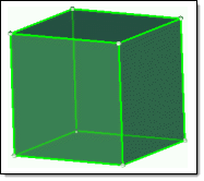
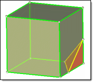
The first cube is mappable in 3 directions, but if 1 corner is split off it becomes
mappable in only 1 direction--and the corner is not mappable without further partitioning.
Engineering Solutions displays the progress of the solid map meshing process in the status bar. Upon completion, Engineering Solutions displays a report of the mesh quality. The element quality value reported is the worst scaled Jacobian in the mesh. The scaled Jacobian's value may range from 0.0 to 1.0(best). An elem's scaled Jacobian is a ratio of the elem Jacobian over the Jacobian of an ideal elem of the same configuration. To use other mesh quality measures, go to the Check Elements panel.
Subpanels and Inputs
The panel includes several subpanels. The General, Line Drag, Linear Solid, and Ends Only subpanels all draw from the same set of input controls (the more specialized panels simply filter out the controls that do not apply to their mapping techniques).
| Note: | All of these subpanels depend on an existing 2D mesh, which is then extrapolated into a 3D mesh based on the parameters you input. The One Volume and Multi Solids subpanels, however, can automatically create 3D mesh directly on solids as long as the solids you select are already mappable. |
|
Use the General subpanel to access all of the possible entry controls for maximum flexibility.
Panel Inputs
Input
|
Action
|
source geom
|
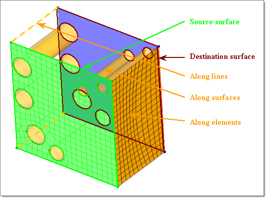
Source geometry that defines the source face of the 3-D volume:
| • | surfs: Select surfaces that define the source face of the volume/solid. |
| • | lines: Select lines that define the periphery of the source face. |
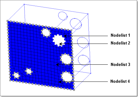
| • | nodes: Select multiple lists of nodes, each representing the periphery of the source face. |
| • | none: No source geometry is defined. The geometry inferred from the elems to drag is considered as source geometry. |
|
elems to drag
|
Select the elements/mesh that correspond to the source face extruded to create the solid mesh. If the source face type chosen is a surface, the elements to drag selection is optional as the elements associated to the surface are automatically selected.
|
dest geom
|
Destination geometry. Select one of the following options from the pop-up menu to provide the geometry that defines the destination face of the 3-D volume:
| • | surfs: Select surfaces that define the destination face of the volume/solid. |
| • | lines: Select lines that define the periphery of the source face. |
| • | nodes: Select multiple lists of nodes, each representing the periphery of the source face. |
|
elems to match / smooth dest
|
| • | elems: Use this selector to pick elements on the destination surface that you wish the 3D mesh to match up with. |
| • | smooth dest: When your destination geometry varies greatly from the source geometry, activate this check box to smooth the mesh that is mapped on the destination face. |
|
along geom
|
Select one of the following options from the pop-up menu to provide the geometry that defines the face of the 3-D volume along which you wish to map the mesh.
| • | surfs: Select surfaces to define the mapping face of the volume/solid. |
| • | lines: Select lines that define the periphery of the source face. |
| • | nodes: Select a node list that defines a line along which to map. |
| • | mixed: Select any combination of surfaces, lines, 2-D elements/shell faces, and/or nodelist/nodepath. When elements are used, the mapped solid mesh maintains the nodal positions with selected elements. They can be equivalenced to have common nodes. While selecting nodelist/nodepath, each selection should represent an edge that connects the source and destination. |
|
along parameters
|
Define/set the parameters required for the mesh along the solid map. Set the element size or density (toggle) to be defined in the along direction. This determines the number of elements along the depth of the mapping. If the size or density is set to "0", the element size/density is calculated based on the average element size of the source elements (elems to drag).
|
along bias style
|
Choose the type of biasing to use while creating nodes in the along direction: linear, exponential, or bellcurve. The biasing style works in conjunction with biasing intensity. If intensity is set to "0" the biasing is not applied. See Bias Styles.
|
intensity
|
Enter the biasing intensity value.
|
|
Use the Line Drag subpanel to select a 2D mesh, and then select a line from the model geometry to use as the mapping direction.
Panel Inputs
Input
|
Action
|
elems to drag
|
Select the elements/mesh that correspond to the source face extruded to create the solid mesh. If the source face type chosen is a surface, the elements to drag selection is optional as the elements associated to the surface are automatically selected.
|
elems to match / smooth dest
|
| • | elems: Use this selector to pick elements on the destination surface that you wish the 3D mesh to match up with. |
| • | smooth dest: When your destination geometry varies greatly from the source geometry, activate this check box to smooth the mesh that is mapped on the destination face. |
|
along geom
|
Select one of the following options from the pop-up menu to provide the geometry that defines the face of the 3-D volume along which you wish to map the mesh.
| • | surfs: Select surfaces to define the mapping face of the volume/solid. |
| • | lines: Select lines that define the periphery of the source face. |
| • | nodes: Select a node list that defines a line along which to map. |
| • | mixed: Select any combination of surfaces, lines, 2-D elements/shell faces, and/or nodelist/nodepath. When elements are used, the mapped solid mesh maintains the nodal positions with selected elements. They can be equivalenced to have common nodes. While selecting nodelist/nodepath, each selection should represent an edge that connects the source and destination. |
|
along parameters
|
Define/set the parameters required for the mesh along the solid map. Set the element size or density (toggle) to be defined in the along direction. This determines the number of elements along the depth of the mapping. If the size or density is set to "0", the element size/density is calculated based on the average element size of the source elements (elems to drag).
|
along bias style
|
Choose the type of biasing to use while creating nodes in the along direction: linear, exponential, or bellcurve. The biasing style works in conjunction with biasing intensity. If intensity is set to "0" the biasing is not applied. See Bias Styles.
|
intensity
|
Enter the biasing intensity value.
|
|
Use the Linear Solid subpanel to select two existing 2D meshes and extrapolate a 3D mesh that connects them.
Panel Inputs
Input
|
Action
|
elems to drag
|
Select the elements/mesh that correspond to the source face extruded to create the solid mesh. If the source face type chosen is a surface, the elements to drag selection is optional as the elements associated to the surface are automatically selected.
|
elems to match
|
Use this selector to pick elements on the destination surface that you wish the 3D mesh to match up with.
|
along geom
|
Select one of the following options from the pop-up menu to provide the geometry that defines the face of the 3-D volume along which you wish to map the mesh.
| • | nodes: Select a node list that defines a line along which to map. |
|
along parameters
|
Define/set the parameters required for the mesh along the solid map. Set the element size or density (toggle) to be defined in the along direction. This determines the number of elements along the depth of the mapping. If the size or density is set to "0", the element size/density is calculated based on the average element size of the source elements (elems to drag).
|
along bias style
|
Choose the type of biasing to use while creating nodes in the along direction: linear, exponential, or bellcurve. The biasing style works in conjunction with biasing intensity. If intensity is set to "0" the biasing is not applied. See Bias Styles.
|
intensity
|
Enter the biasing intensity value.
|
|
Use the Ends Only subpanel to select two opposing surfaces and one 2D mesh, then extrapolate the mesh between the surfaces.
Panel Inputs
Input
|
Action
|
source geom
|
Source geometry that defines the source face of the 3-D volume:
| • | surfs: Select surfaces that define the source face of the volume/solid. |
| • | lines: Select lines that define the periphery of the source face. |
| • | nodes: Select multiple lists of nodes, each representing the periphery of the source face. |
| • | none: No source geometry is defined. The geometry inferred from the elems to drag is considered as source geometry. |
|
dest geom
|
Destination geometry. Select one of the following options from the pop-up menu to provide the geometry that defines the destination face of the 3-D volume:
| • | surfs: Select surfaces that define the destination face of the volume/solid. |
| • | lines: Select lines that define the periphery of the source face. |
| • | nodes: Select multiple lists of nodes, each representing the periphery of the source face. |
|
elems to drag
|
Select the elements/mesh that correspond to the source face extruded to create the solid mesh. If the source face type chosen is a surface, the elements to drag selection is optional as the elements associated to the surface are automatically selected.
|
elems to match / smooth dest
|
| • | elems: Use this selector to pick elements on the destination surface that you wish the 3D mesh to match up with. |
| • | smooth dest: When your destination geometry varies greatly from the source geometry, activate this check box to smooth the mesh that is mapped on the destination face. |
|
along parameters
|
Define/set the parameters required for the mesh along the solid map. Set the element size or density (toggle) to be defined in the along direction. This determines the number of elements along the depth of the mapping. If the size or density is set to "0", the element size/density is calculated based on the average element size of the source elements (elems to drag).
|
along bias style
|
Choose the type of biasing to use while creating nodes in the along direction: linear, exponential, or bellcurve. The biasing style works in conjunction with biasing intensity. If intensity is set to "0" the biasing is not applied. See Bias Styles.
|
intensity
|
Enter the biasing intensity value.
|
|
Use the One Volume subpanel to select a single mappable solid volume and create a new 3D mesh for it.
Panel Inputs
Input
|
Action
|
volume to mesh
|
Select the solid to mesh.
|
source hint
|
This is the “beginning” surface, to define the direction of mesh mapping.
|
dest hint
|
This allows you to specify the “ending” surface, to define the direction of mesh mapping.
|
source shells
|
This defines the 2d mesh on the initial surface of the solid, and will dictate the output element type when meshing the solids.
| • | mixed: the resulting output solid mesh will consist of hexa’s and penta elements. |
| • | quad: only hexa’s will be created |
| • | trias or R-trias: only penta’s will be created (right-angle pentas in the case of R-trias). |
|
along geom
|
Select one of the following options from the pop-up menu to provide the geometry that defines the face of the 3-D volume along which you wish to map the mesh.
| • | surfs: Select surfaces to define the mapping face of the volume/solid. |
| • | lines: Select lines that define the periphery of the source face. |
| • | nodes: Select a node list that defines a line along which to map. |
| • | mixed: Select any combination of surfaces, lines, 2-D elements/shell faces, and/or nodelist/nodepath. When elements are used, the mapped solid mesh maintains the nodal positions with selected elements. They can be equivalenced to have common nodes. While selecting nodelist/nodepath, each selection should represent an edge that connects the source and destination. |
|
along parameters
|
Define/set the parameters required for the mesh along the solid map. Set the element size or density (toggle) to be defined in the along direction. This determines the number of elements along the depth of the mapping. If the size or density is set to "0", the element size/density is calculated based on the average element size of the source elements (elems to drag).
|
along bias style
|
Choose the type of biasing to use while creating nodes in the along direction: linear, exponential, or bellcurve. The biasing style works in conjunction with biasing intensity. If intensity is set to "0" the biasing is not applied. See Bias Styles.
|
intensity
|
Enter the biasing intensity value.
|
smooth dest
|
This smooths the elements on the resulting face of the solid to improve the resulting mesh quality.
|
elems to solid/surf comp / elems to current comp
|
Select which component to put the newly-created elements:
| • | elems to solid/surf comp: the elements will be added to the same component that contains the solid and its surfaces. |
| • | elems to current comp: the new elements will be added to the current component shown in the status bar. |
|
|
Use the Multi Solids subpanel to select multiple mappable solids and create 3D meshes for them.
Engineering Solutions can create volume meshes on multiple shapes at the same time, allowing you to mesh solid parts faster.
| Note: | Complex parts must still be partitioned into multiple simpler solids. |
|
It is also important to note that this does not always work for large numbers of solids--even if they are all mappable, in some cases you may need to mesh them a few at a time or even (in extreme cases) individually.
Panel Inputs
Input
|
Action
|
solid
|
Pick the desired solids. Only solids that are mappable can be meshed; see partitioning solids for mappability for details on how to determine what is mappable and to subdivide complex solids into simpler, mappable ones.
|
interactive / automatic
|
| • | automatic: the 3D solid mesh is created immediately. |
| • | interactive: several subpanels are presented to enable finer control over the mesh density and element mesh patterns. |
|
elem size
|
Size to be used when initially distributing the nodes to the edges.
|
source shells
|
This defines the 2d mesh on the initial surface of the solid, and will dictate the output element type when meshing the solids.
| • | mixed: the resulting output solid mesh will consist of hexa’s and penta elements. |
| • | quad: only hexa’s will be created |
| • | trias or R-trias: only penta’s will be created (right-angle pentas in the case of R-trias). |
|
source hint
|
This is the “beginning” surface, to define the direction of mesh mapping.
|
dest hint
|
This allows you to specify the “ending” surface, to define the direction of mesh mapping.
|
elems to solid/surf comp / elems to current comp
|
Select which component to put the newly-created elements:
| • | elems to solid/surf comp: the elements will be added to the same component that contains the solid and its surfaces. |
| • | elems to current comp: the new elements will be added to the current component shown in the status bar. |
|
smooth dest
|
This smooths the elements on the resulting face of the solid to improve the resulting mesh quality.
|
apply orthogonality to along
|
This will keep the solid elements generated more perpendicular to the surface faces in the along direction.
|
stop meshing on bad jacobian
|
This halts the meshing routines upon the creation of a bad jacobian solid element.
|
previous settings
|
This will cause the mesh to honor any prior edge node density settings when creating the temporary surface mesh.
|
Clicking mesh in this panel will create the solid mesh if automatic mode had been selected. If the interactive mode was selected, it will create any temporary 2D shell meshes required and assign the node seeding density to all of the along edges. Then it will open the density subpanel.
Use the Multiple Solids Density subpanel to interactively adjust the node density along any of the edges within the solid. The edges are organized into groups of edges. Each group must preserve a certain relationship between the number of nodes on each of the edges within the group. This means that when the density of an edge within this group is increased by 1, all of the edges within this group will have their density increased by 1.
To facilitate finer control over the appearance of the final solid mesh, any surface mesh which will be required to generate the final solid mesh will be visible during this stage. Any change to edge densities affecting the edges of one of these surface meshes will cause the surface mesh to be immediately recalculated and displayed. However, this applies only to meshes generated during the current meshing operation. Any 2D surface mesh which was generated prior to entering the Solid Map panel will not be allowed to change the node density along its edges; these "locked" density numbers have a parenthesis () around them. If these surfaces require a change in edge density, it must occur prior to entering the Solid Map panel. Any edge whose density was calculated using the element size will be indicated by an asterisk * placed before the density number.
The controls for interactively adjusting the node densities along edges are identical to those used within the density subpanel of the 2D Automesh panel. You can either choose to toggle densities up and down, assign them based upon element size or assign a specific density value to any selected edge. Unlike the 2D Automesh panel, the 2D meshes within the multiple solids panel will be instantly updated with any change in edge density.
To update the node seeding on 2D meshed solids:
| 1. | Select the edge collector in by adjustment. |
Holding down the left mouse button and passing the cursor over an edge causes the entire edge group to pre-highlight. Once a group of edges is selected, the element density number appears on each of these edges; clicking the number with the left mouse button raises the density, while clicking with the right mouse button lowers it. Holding the mouse button down on the density number, then sliding the cursor up and down makes rapid changes to the density number.
| 2. | Optional: select the edge collector in by elem size. |
This allows for the automatic calculation of the element density based upon the element size below.
| 3. | Optional: select the edge collector in by density. |
This allows for the assignment of the element density based upon the user-defined density below.
This will create the solid mesh with the current node density settings.
|
Use the Multiple Solids Face Style subpanel to interactively adjust the element type (tria, quad, mixed …), the meshing algorithm (including the assignment of which 4 vertices should be used to define the corners on a quad-shaped surface containing more than 4 vertices), and an assortment of other meshing parameters. This allows you to improve the appearance and quality of the 2D shell mesh while maintaining the existing edge densities.
| 1. | Optional: in the element type column, selecting either the toggle surf collector or the set surf collector allows your to switch the surface mesh element type between trias, quads or mixed. |
| 2. | Optional: in the mesh method column, selecting the toggle surf collector switches the selected surface meshing type (algorithm) between mapped and unmapped. |
| 3. | Optional: in the mesh method column, selecting the 4 map corners collector allows you to select the 4 corners to be used when meshing a surface with the quad mappable algorithm. |
The surface can have more than 4 “corner” points and is recognized by the uniqueness of its corner points.
| 4. | Optional: in the mesh flags column, selecting the set surf collector then selecting a surface within the model shows the parameters currently enabled on the selected surface (by means of the status of the checkboxes). Checking or un-checking any of the parameters (flow: align or size, map: size or skew) will immediately update the mesh to reflect the change in the meshing parameters. |
This creates the solid mesh with the current face style settings.
|
Use the Multiple Solids Options subpanel to adjust a number of graphic display options and mesh parameter options. The graphic display options are useful for limiting the amount of information displayed to the screen, since some of the information is not routinely required. The mesh parameter options are the same options available on the multiple solids panel.
| 1. | Optional: activate the checkbox for show sequence ids. |
This shows the sequence the meshing routine will take when solid-meshing the part. Each solid will have a sequence number and a line indicating the direction of the meshing. The meshing of the solids will proceed from 1 to the highest sequence number.
This is a useful debugging tool to see how the meshing operation will take place; for example, if the meshing operation fails the sequencing numbers can be displayed on the screen, and looking at this series may highlight problems in the model. To resolve such problems, further partitioning of the solids may be necessary.
| 2. | Optional: activate the checkbox for show nodal distribution. |
This marks all of the edges affected by an operation which changes the edge’s density with yellow temporary nodes. Otherwise, only the density number will show the change.
| 3. | Optional: activate the checkbox for show num on all edges. |
This places the number representing the element density on all of the solid’s edges. Otherwise only the density numbers of the current group of edges will be shown.
| 4. | Optional: activate the checkbox for show current solids only. |
This masks all of the solids in the display except for the ones initially selected when entering the multiple solids panel.
| 5. | Optional: activate the checkbox for Show solid id. |
This shows each solid's id number in the graphics area--useful if you wish to edit or delete a mesh associated with a specific solid.
| 6. | Optional: activate the checkbox for show master surf mesh type. |
This places the mesh type icon on each of the surfaces with a 2D mesh.
| 7. | Optional: activate the checkbox for hide mapped type. |
This hides all of the mesh type icons for mapped surfaces, making it easier to see which surfaces are not mappable.
|
|
The following action buttons appear throughout the subpanels:
Input
|
Action
|
mesh
|
Create a solid mesh with all the provided input. The solid mesh created is placed in a collector named solidmap. If that collector does not exist, a new component is created with that name.
|
reject
|
Rejects the last mapped solid mesh created.
|
equiv/faces
|
Equivalences all the elements in the solidmap component and creates the faces (^faces component) for that component. This function is optional and does not directly impact the solidmap functionality. It allows you to perform faster and easier solid modeling. The solidmap component is equivalenced with an initial tolerance of 1% of element size. When this function is performed, a message is displayed informing you of the number of nodes equivalenced along with the tolerance value used. Any subsequent use of this function without performing additional solid mapping increases the tolerance (to a maximum of 10% element size) before equivalencing again.
|
return
|
Exits the panel.
|
|
Comments
You can omit the source, the destination, or the along geometry by setting either one of the entity selectors to (none). Only one of these selections can be set to (none); the other two selections are then required to define the volume to fill.
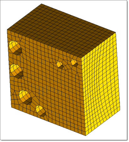
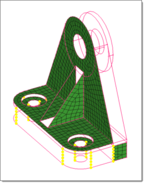
The 2-D meshes extruded do not have to be continuous (note the hole in the mesh in the example above).
The "along" faces do not all have to be defined.
You can create elements with a user-specified bias by selecting linear, exponential, or bellcurve after bias style:. Enter the bias intensity value after intensity = and click mesh.
See Also:
Partitioning solids for mappability