Use the Features panel to identify geometric features of a finite element model based on the relative angle between adjacent elements. Features are displayed by creating one-dimensional plot elements or feature lines. It provides a visualization tool which enables you to see the edges of a complex model where the normals of adjacent elements differ by more than a user-specified feature angle. If your mesh contains adjoining elements with normals pointing in opposite directions, features can be created between those elements (even if their true feature angle is less than specified). Features can be used to approximate the original surface face and patch boundaries of the geometry used to create the mesh.
Panel Usage
The Features panel contains separate subpanels for creating features and editing them.
Some functions, such as creating geometric surfaces from existing finite element mesh, allow you to choose plot elements to represent the surface delineations. This function works well only when the selected plot elements are closed loops. You can use the Edges, Features, and the Edit Element panels to create these plot elements. But the Features panel does not always create closed loops of plot elements. The Edit subpanel in this Features panel allows you to quickly close the open loops of features (plot elements).
Comments
All the feature plot elements or feature lines created are placed in a temporary collector called ^feature. This collector will not be written to the solver deck upon export.
Any attempt to create new features empties the ^feature collector, deleting all earlier features. If you want to save the features, move them to another collector or rename the ^feature collector.
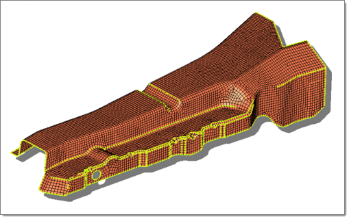
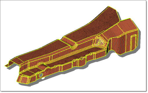
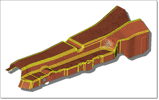
Examples
The following images depict the results using different options available:
Simple
|
Advanced
|
Small Areas Merged

|
Connected
|
Subpanels and Inputs
The Features panel contains the following subpanels and command buttons:
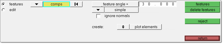
Use the Features subpanel to identify features and create feature lines for them.
Panel Inputs
Input
|
Action
|
entity selector
|
Select the type of entity that you wish to pick. Choices are elems or comps.
|
feature angle
|
Enter a number of degrees. This defines the maximum angle you wish to allow between the normals of two connected plate elements. When such an angle exceeds this value, a plot element is generated.
|
recognition method
|
Select the type of analysis to perform when extracting feature lines:
| • | Simple provides a fast method of identifying features based solely on the angle between normals of adjacent elements. |
| • | Advanced takes into account additional logic to create closed loops of feature elements. In addition, if you intend to convert features to surfaces later, the conversion to surfaces will go much faster. It also usually creates more features than simple analysis does. |
| • | Connected: This method seeks to avoid any "orphan" or non-closed feature lines. It works similarly to Advanced, but includes a more rigorous check to combine small areas and avoid creating features that end abruptly or do not connect to any other features. |
|
ignore normals
|
Check ignore normals to disregard the "direction" of the elements when creating features. This means that the elements’ positive normal directions will not be considered while creating geometry features.
|
merge small areas
|
Appears when the analysis type is advanced. When this option is active, small areas will be combined; for example, a long but narrow strip that might result in two parallel feature lines very close to one another would instead create only one feature line. The value you enter is the ratio between areas of the feature patches that will be combined--so the smaller the value entered, the more areas will be combined.
|
create: plot elements / lines
|
Choose between creating plot elements or lines.
|
smooth
|
Appears when you choose to create lines. Check this box to create smooth (curved) lines rather than jointed ones.
|
break angle
|
A value above which a line will be broken into two lines with a joint between them.
|
|
Use the Edit subpanel to make changes to existing features.
Panel Inputs
Input
|
Action
|
node to add feature: node list selector
|
Select a node list to manually extend feature lines. Individual nodes can be selected, or a node path selector can be used to automatically connect a series of nodes.
|
element features to remove: elem selector
|
Remove plot elements from the feature. Any extraneous plot elements or unnecessary features identified can be removed by selecting them with the elems collector. Once a single plot element of a feature is selected, the remaining elements of that feature line will automatically be selected.
|
move into ^open features
|
When using find all open features, clicking this button places all located open features or loops into a component called ^open_features.
|
interactive review / find all open features
|
Choose between reviewing open feature ends or loops one at a time, or allowing HyperMesh to automatically locate all of them at once.
|
review opened element features: continue/restart
|
When using interactive review, selectively identify any open feature ends or loops. The open feature will be highlighted and the unconnected end will be identified with a red circle.
Continue will sequence from one open feature to the next.
Restart review will restart the check calculations from the beginning to find any additional open features
|
displayed size
|
Set the display radius (in model units) of the open feature during review. A smaller value will zoom in closer to the open feature.
Put another way, this value determines how much of the surrounding model displays during the review.
|
|
The following action buttons appear throughout the subpanels:
Button
|
Action
|
features
|
Displays the features of the selected components. A component named ^feature is created if it does not already exist, and all plot elements or lines created are placed into this component.
|
delete features
|
Deletes all features regardless of what may have occurred since they were generated.
|
continue
|
If the model contains open feature loops, Engineering Solutions highlights the first, places a red circle at the free end of the feature, and updates the display so that you can see the feature easily. You can click continue as many times as necessary to review all open loops.
|
restart review
|
Restarts the review of open loops.
|
add
|
Adds the selected entities to the feature.
|
remove
|
Removes the entire highlighted feature.
|
reject
|
Reverts all created features, if you have not left the panel or performed more creations in the meantime.
|
return
|
Exits the panel.
|
|
See Also:
Alphabetical List of Panels


