Use the Interfaces panel to create and modify interfaces. Interfaces are mainly used to define contact interactions between various parts of the model.
Panel Usage
The Interfaces panel is divided into multiple subpanels, each geared toward a separate task. Settings made on each subpanel are persistent until you exit HyperMesh--changing subpanels will not reset any inputs.
Created interfaces are stored in the database as groups. In addition to defining contact interactions, the Interfaces panel can be used to define a variety of solver-specific constraints output requests, and so on. Due to a large variation in the way various solvers define these interfaces, you are required to load the necessary solver template while using this panel.
The types of interfaces and the corresponding entities used to define each type of interface are defined by the solver template. The following solver templates use this panel to define interfaces: Abaqus; LS-DYNA; MADYMO; Nastran; PAM CRASH 2G, and RADIOSS. HyperMesh templates can be designed to work with dictionaries (old) or card images (new). The Interfaces panel behaves differently for templates with dictionaries verses those defined with card images. Since most of our solver templates use card images (Abaqus, LS-DYNA; MADYMO; Nastran; PAM CRASH 2G, RADIOSS, and so on), the panels are described below for use with the new templates that use card images.
Subpanels and Inputs
The Interfaces panel contains the following subpanels and command buttons:
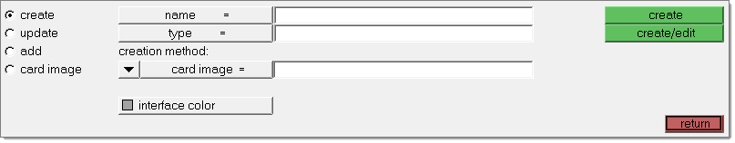
Use the Create subpanel to create a new interface (contact).
Panel Inputs
Input
|
Action
|
name =
|
Enter the name of the new interface to be created in the entry field, or select an interface from the list of existing interfaces. To select an existing interface: double-click on name = and select one of listed interfaces. This field is repeated in all subpanels.
|
type =
|
This field should be used in conjunction with the connection method field. For templates that are developed with card images (Abaqus, LS-DYNA; MADYMO; Nastran; PAM CRASH 2G, and RADIOSS), the type and card image field should match.
| • | To select a type for a new interface: click type= and select a type from the pop-up list. The different interface types are defined by the template. Make sure you have the right template loaded before selecting a type. |
| • | While creating an interface by copying from an existing interface, using the same as creation method, the type = field is automatically updated to be same as the type of the existing interface. |
|
creation method
|
This field should be used in conjunction with the type= field. For templates that are developed with card images (Abaqus, LS-DYNA; MADYMO; Nastran; PAM CRASH 2G, and RADIOSS), the type and card image field should match. The following options are available:
| card image = | This option is used for creating an interface with the selected card image. This field is automatically updated (to be same as type) as soon as you pick a type in type= field. |
| same as = | This method is used to create interfaces by copying the card image (and all its attributes) from an existing interface. You can select an existing interface from which to copy by clicking same as = and selecting interfaces from the list. With this method, the type= field is updated to match the type of the existing selected interface. The new interface is not linked to the original one at any time. Only its card image and type are copied while creating the new interface. Once the new interface is created, updates to the old interface do not affect the new one. |
| no card image | This method is for templates that are developed using dictionaries (for example, CMOLD and PATRAN). This option is not valid for templates with card images (Abaqus, LS-DYNA; MADYMO; Nastran; PAM CRASH 2G, and RADIOSS). |
|
interface color
|
Click interface color to choose the color of the new interface to be created. The new interface is displayed in the graphics using this color. The color is updated to the same as = interface color as soon as you pick the existing interface. You are allowed change this color to a color other than the same as = interface color.
|
|
Use the Update subpanel to update/change the type and color of an existing interface.
Panel Inputs
Input
|
Action
|
name =
|
Select the necessary interface from the list of existing interfaces. To select an existing interface, double-click name= and select one from the list. This field is repeated in all subpanels.
|
type =
|
Select the new type to which you want the interface updated. Click type= and select a type from the pop-up list. The different interface types are defined by the template. Please make sure you have the right template loaded before selecting a type.
|
interface color
|
Click here and choose the new color to be assigned to the interface.
|
|
Use the Add subpanel to add and/or update all the entities (elements, nodes, comps, sets, and so on) that define an interface. Depending on its type, an interface can contain:
| • | Master and slave entities |
The various types of entities that can be added to master and/or slave are:
| • | Entity: individual nodes or elements (the type of interface determines if it is nodes or elements) |
| • | Face: faces of solid elements |
| • | Csurfs: contact surfaces |
Not all types of entities can be added to all interfaces. The type of interface determines the add entities that are valid. Loading the solver-specific user profile automatically updates this panel to show only the valid add options for each interface type. The following options are available in this subpanel:
Panel Inputs
Input
|
Action
|
name =
|
To select an existing interface, double-click name = and select an interface from the list. This field is repeated in all subpanels. Depending on the type of interface selected, either both master and/or the slave are available for adding entities. If the selected interface has master and/or slave entries added previously, the panel will be updated to show that master/slave type.
|
master
|
Select the master type from the pop-up list of entities. The corresponding entity collector (for example, comps, nodes, and so on) is available for selecting the entities from the display or via the extended entity selection methods. Then click add/update (add if master type is entity; update for all other master types) to add the entities to the interface. The master types include:
entity
|
Allows you to add individual elements or nodes to the interface. The selected elements or nodes are used to create master elements in the interface. While creating these master elements (by duplicating the selected elements), you can choose to maintain or reverse their normals relative to the original elements (by activating the reverse check box next to element collector).
|
face
|
Allows you to add faces of solid elements to define the interface. Select the solid elements and face nodes (at least three nodes). The faces that are added to the interface are determined as follows:
The face nodes (at least three nodes that are part of the same face of a solid) selected are used to identify the starting face of the solid. The adjacent faces (of selected solid elements) are identified. If the angle between the normals of these adjacent faces is less than the break angle specified, those faces are also added to the interface. This process continues until all of the faces of selected elements have been tested. You can choose multiple sets of three face nodes to add multiple faces to the interface. Master elements are created for each face that is added to the interface.
|
comps
|
Allows you to add components to the interface.
|
csurfs
|
Allows you to add contact surfaces to the interface.
|
sets
|
Allows you to add entity sets to the interface.
|
all
|
Allows you to define an interface that encompasses the entire model. This option does not add any entities to the interface. It turns on a flag that is used by the solver templates that support this option.
|
|
slave
|
Select the slave type from the pop-up entity list. The corresponding entity collector (for example, comps, nodes, and so on) is available for selecting entities from the display or via extended entity selection methods. Then click add/update (add if the slave type is entity; update for all other slave types) to add the entities to the interface. The slave types include:
entity
|
Allows you to add individual elements or nodes to the interface. The selected elements or nodes are used to create slave elements in the interface. While creating these slave elements (by duplicating the selected elements), you can choose to maintain or reverse their normals relative to the original elements (by activating the reverse check box next to element collector).
|
face
|
Allows you to add faces of solid elements to define the interface. Select the solid elements and face nodes (at least three nodes). The faces that are added to the interface are determined as follows:
The face nodes (at least three nodes that are part of the same face of a solid) selected are used to identify the starting face of the solid. The adjacent faces (of selected solid elements) are identified. If the angle between the normals of these adjacent faces is less than the break angle specified, those faces are also added to the interface. This process continues until all of the faces of selected elements have been tested. You can choose multiple sets of three face nodes to add multiple faces to the interface. Slave elements are created for each face that is added to the interface.
|
comps
|
Allows you to add components to the interface.
|
csurfs
|
Allows you to add contact surfaces to the interface.
|
sets
|
Allows you to add entity sets to the interface.
|
all
|
Allows you to define an interface that encompasses the entire model. This option does not add any entities to the interface. It turns on a flag that is used by the solver templates that support this option.
|
|
|
Use the Card Image subpanel to view, edit, update/change, and reset the card image of an interface. This subpanel requires that you load a solver template and does not impact templates using dictionaries.
Panel Inputs
Input
|
Action
|
name =
|
Select an interface from the list of existing interfaces. To select an existing interface, double-click name= twice and select one from the list. This field is repeated in all subpanels. The corresponding card image is automatically filled as soon as you pick the interface.
|
card image =
|
Allows you to choose a new card image to apply to the interface.
|
|
The following action buttons appear throughout the subpanels:
Button
|
Action
|
create
|
Creates a new interface with the name and type chosen.
|
create/edit
|
Creates a new interface with the name and type chosen and shows the card image of the interface. This allows you to update any field in the interface card.
|
update type
|
After you select the name= and type= of the appropriate interface, click update type to update the selected interface to the new type. For templates that are developed with card images (Abaqus, LS-DYNA, MADYMO, Nastran, PAM CRASH 2G, and RADIOSS), the type and card image field should match. Therefore, updating the type automatically updates the card image.
|
reject type
|
Click reject type to reject (undo) the latest change to the interface type and revert to the previous type. The update can only be rejected as long as you remain in the same panel/subpanel.
|
update color
|
After you select the name = and new interface color of the appropriate interface, click update color to update the selected interface to the new color.
|
review
|
Click review after you selected the interface to graphically view the entities in the interface. All the master entities of the interface are displayed in blue and the slave entities in red. The remaining model is drawn in gray. This review mode is a temporary graphics mode. The display returns to its original graphics with component colors, if you return out of the panel, select another interface for name =, or click review a second time.
In review mode, review opts allows you to customize the graphical review of the interfaces.
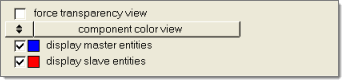
The following options are available in review opts:
| • | force transparency view: When turned on, displays the entities that are not part of the interface in a transparent view so that the master and slave entities in the interface can be easily viewed. |
| • | component color view/gray color view: When component color is selected, the entities that are not part of the interface are displayed in their original component color. When gray is chosen, the entities that are not part of the interface are displayed in gray, improving the highlighting of the master and slave entities. |
| • | display master entities: Allows you display on/off the master entities while in the review mode. This check box has on affect on the actual display of master entities in the Display panel. |
| • | display slave entities: Allows you display on/off the slave entities while in the review mode. This check box has on affect on the actual display of slave entities in the Display panel. |
|
normals
|
Displays the normals of elements selected. Click normals and then select an element in the display. The normal vector of that element is drawn on the display. You can continue selecting more elements to view their corresponding normals. The normal direction of the master and slave entities is important for defining the contact interactions correctly. This review of normals enables you to choose to reverse or maintain the normals of original elements while adding master and slave entities.
|
add
|
Add the specified entities to the interface.
| Note: | Separate add buttons exist for master and slave entities. |
|
load
|
Loads the selected card image to the interface. This function allows you to load/update multiple interfaces with the selected card image. Once you click load, you can choose one or more interfaces to update. This function does not consider the interface in the name = field to load the new card image. For templates that are developed with card images (Abaqus, LS-DYNA; MADYMO; Nastran; PAM CRASH 2G, and RADIOSS), the card image and type should match. Therefore, loading a new card image automatically updates its type to match.
|
load/edit
|
Loads the selected card image to the interface selected in the name = field and shows the card image of that interface. This allows you to update any field in the interface card.
|
edit
|
Shows the card image of the selected interface, allowing you to update any of its entries.
|
reset
|
Resets the card image of selected interface to no card image.
|
reset all
|
Resets all the card images of the selected interface to no card image. Interfaces are allowed to have only one card image per solver template. But if a model has been converted between multiple solvers, it is possible for an interface to have multiple card images, each belonging to a different solver template. This function resets all of them to no card image.
|
return
|
exits the panel.
|
|


