Use the HyperBeam panel to create beam cross-section entities that you can use to simplify complex portions of your model into simple bar elements.
Panel Usage
The HyperBeam panel is organized into several subpanels. The settings on each subpanel are persistent--you will not lose work if you switch to a different subpanel and then switch back. Each subpanel covers a different type of beam section, except for the more general edit section and section utils (utilities) subpanels.
The standard method to use to create beam cross section entities is as follows:
| 1. | Define a planar cross-section cutting through the region. |
| 2. | Create a cross-section entity to hold that information. |
| 3. | Use this panel to select the cross-section entities to generate a cross-section definition. It is also possible to create a node at the section centroid or shear center. |
| 4. | Use the HyperBeam module to view and edit this data, specifying metal thicknesses, and additional related information. |
| 5. | Use the HyperBeam module to calculate its mechanical properties. |
| 6. | Create a property on the Collectors panel appropriate for your bar elements. |
| 7. | Assign this beam section to that property. |
| 8. | Use the node created in step 3 to create a bar element that uses the above property. |
Depending on your solver, you may need to return to the HyperBeam module to adjust the origin of the local coordinate system that it uses to calculate the properties, to account for the intrinsic offsets of the bar element.
Another option is to use the coordinates of the centroid as the offsets on the bar element.
There are four types of beam cross-sections that HyperBeam recognizes, and each is represented by a subpanel.
Subpanels and Inputs
The HyperBeam panel contains the following subpanels and command buttons:
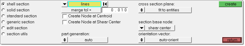
A thin-shell cut through one or more separate pieces of sheet metal. When HyperBeam calculates their section properties, it uses thin-shell finite element theory.
Panel Inputs
Input
|
Action
|
use lines / use elems
|
The lines or elements from which you wish to create a beam section. These must be in the form of a perpendicular cut through a part made of welded pieces of sheet metal or similar.
|
section cut
|
To create a shell section, cut through the selected entities at the plane location and then use the resulting section lines. Engineering Solutions centers the beam section at the centroid of the section, the shear center, or at an arbitrary point that you define. Optionally, you can create nodes at the centroid and shear center of the beam section.
The section plane normal forms the beam section’s local x-axis (length) and the orient vector forms the beam section’s local y-axis (height).
Additionally, you can assign a boundary. Engineering Solutions will crop the section lines where they cross the boundary. For shell beam section, Engineering Solutions will discard the portions of the section lines which lie outside the boundary.
|
merge tol =
|
This value is used to determine if nodes or the ends of lines are coincident when generating the cross-section for HyperBeam.
|
Create node at centroid:
|
Activate this option to create a node at the section's centroid.
|
Create node at Shear Center:
|
Activate this option to create a node at the section's shear center.
|
part generation
|
Determine how the lines or elements will be sorted:
| • | To sort lines and elements into their separate sheet metal parts, set part generation to auto. |
| • | To force every separate line or element to be a separate sheet metal part, set part generation to simple. |
|
cross section plane:
fit to entities /
project to plane
|
When set to fit to entities, then use the section base node switch to specify the origin to use for the system.
To specify the plane yourself, set the toggle to project to plane and specify the plane to use, then use the section base node switch to specify the origin to use for the system.
|
section base node:
|
Pick where to locate the section base node. This helps determine its orientation.
The options are centroid, shear center or a selected node.
|
orientation vector:
|
The section is oriented normal to this vector at the specified base node.
| • | auto-orient determines the orientation automatically. |
| • | Alternatively, toggle to the plane and vector selector to pick an existing vector entity, one of the default system axes, or to specify a plane to which the vector will be normal. |
|
Undo
There is no reject function for this procedure. Use the HyperBeam module or the Model browser's context menu to delete a newly created beam section.
Comments
In the background, the lines are meshed with plot elements and passed to HyperBeam. HyperBeam then uses planar thin shell theory to calculate their section properties.
A "part" is a grouping of those plot elements that share a common metal thickness.
|
Cuts through cast or molded parts, or when the sheet metal thicknesses are so large that thin-shell theory is inappropriate. When HyperBeam calculates their section properties, it uses planar solid finite element theory.
Panel Inputs
Input
|
Action
|
elems / lines / surfs
|
Select the surface, lines or elements that form the solid section. These must be in the form of a perpendicular cut through a solid part. The only elements recognized are trias and quads.
|
section cut
|
To create a solid type beam section, cut through the selected entities at the plane location and then use the resulting section lines. Engineering Solutions centers the beam section at the centroid of the section, the shear center, or at the arbitrary point that you define. Optionally, you can create nodes at the centroid and shear center of the beam section.
If you are creating a solid beam section, Engineering Solutions will fill the interior of the section lines with beam section elements, as long as the section lines form one or more loops.
The section plane normal forms the beam section’s local x-axis (length) and the orient vector forms the beam section’s local y-axis (height).
Additionally, you can assign a boundary. Engineering Solutions will crop the section lines where they cross the boundary. For solid beam sections, Engineering Solutions will use the boundary in place of the portions of the section lines, which lie outside the boundary when the section is being filled in.
|
merge tol =
|
This value is used to determine if nodes or the ends of lines are coincident when generating the cross-section for HyperBeam.
|
Create node at centroid:
|
Activate this option to create a node at the section's centroid.
|
Create node at Shear Center:
|
Activate this option to create a node at the section's shear center.
|
analysis type:
|
This toggle determines the order of quads or trias used: first order or second order.
|
cross section plane:
fit to entities /
project to plane
|
When set to fit to entities, then use the section base node switch to specify the origin to use for the system.
To specify the plane yourself, set the toggle to project to plane and specify the plane to use, then use the section base node switch to specify the origin to use for the system.
|
section base node:
|
Pick where to locate the section base node. This helps determine its orientation.
The options are centroid, shear center or a selected node.
|
orientation vector:
|
The section is oriented normal to this vector at the specified base node.
| • | auto-orient determines the orientation automatically. |
| • | Alternatively, toggle to the plane and vector selector to pick an existing vector entity, one of the default system axes, or to specify a plane to which the vector will be normal. |
|
Undo
There is no reject function for this procedure. Use the HyperBeam module or the Model browser's context menu to delete a newly created beam section.
Comments
In the background, the lines or surfaces are meshed with quad and tria elements and passed to the HyperBeam module. HyperBeam then uses planar solid finite element theory to calculate their section properties.
|
Use the Standard Section subpanel to quickly generate models using a few standard shapes such as boxes or tubes. HyperBeam uses the closed-form equations for their section properties.
Panel Inputs
Input
|
Action
|
standard section library:
|
Use this switch to pick the solver for which you wish to create a standard section.
This determines the options available for standard section type.
|
standard section type:
|
Select the standard beamsection you wish to create. the options available depend on the solver library chosen for standard section library.
|
Undo
There is no reject function for this procedure. Use the HyperBeam module or the Model browser's context menu to delete a newly created beam section.
Comments
HyperBeam calculates the section properties of the chosen standard section using closed-form equations.
|
Included for backward compatibility with older models. For these, you have to explicitly enter all of the necessary quantities for the section properties.
There are no inputs on this subpanel; clicking create opens a new generic section in the HyperBeam View of the Model browser, allowing you to specify the section properties.
|
Use the Edit Section subpanel to open the selected cross-section in HyperBeam for review or modification.
This subpanel contains only a single input: a beamsect collector. Use this to select the desired beam section, then click edit to open the selected section in the Model browser's HyperBeam View.
|
Use the Section Utils subpanel to find and mark unreferenced sections, automatically connect shell sections, or position shell or solid sections.
Panel Inputs
Input
|
Action
|
(function switch)
|
Use the first switch on the subtab to determine the type of operation you wish to perform: mark unreferenced sections, auto-connect shell sections, or position shell/solid sections.
|
beamsects
|
This collector displays when the function switch is set to auto-connect shell sections, or position shell/solid sections. Use it to select the beam sections that you wish to connect or position.
|
tolerance =
|
This numeric box displays when the function switch is set to auto-connect shell sections. Sections within this distance from each other will be connected.
|
thickness =
|
This numeric box displays when the function switch is set to auto-connect shell sections.
|
at shear center / at centroid / translate
|
This location switch displays when the function switch is set to position shell/solid sections. It determines where the beam section will be repositioned to.
|
y val =
|
This numeric box displays when the function switch is set to position shell/solid sections and the location switch is set to translate.
This is the distance to move the beam section along the Y axis.
|
z val =
|
This numeric box displays when the function switch is set to position shell/solid sections and the location switch is set to translate.
This is the distance to move the beam section along the Z axis.
|
|
The following action buttons appear throughout the subpanels:
Button
|
Action
|
create
|
Creates the beamsection entity based on the specified inputs.
|
edit
|
Opens the selected beamsection in the Model browser's HyperBeam View.
|
save referenced
|
Saves a list of referenced beamsections in memory for retrieval on other panels via the extended entity selection menu's retrieve option.
|
save unreferenced
|
Saves a list of unreferenced beamsections in memory for retrieval on other panels via the extended entity selection menu's retrieve option.
|
connect
|
Auto-connects the specified beam sections based on the specified tolerance and thickness.
|
position
|
Repositions the specified beam sections based on the specified location inputs.
|
return
|
Exits the panel.
|
|
See Also:
Alphabetical List of Panels


