Engineering Solutions

Composites panel

Composites panel

Previous topic Next topic Expand/collapse all hidden text  

Composites panel

Previous topic Next topic JavaScript is required for expanding text JavaScript is required for the print function  

Use the Composites panel to assign and review the element material orientation of a mesh of shell and continuum shell elements or to review the fiber direction (ply angle) of individual composite layers. The normal direction of elements is essential for the stacking direction of plies and thus is accessible directly from the Composites panel as well.

A valid user profile must be selected for the Composites panel to function properly. Currently, valid analysis templates include:

OptiStruct
ANSYS
Abaqus
Nastran


Panel Usage


The Composites panel consists of three subpanels to handle element normals, material orientations and ply directions.

composites_panel

Subpanels and Inputs


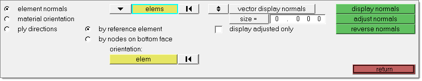
The Composites panel contains the following subpanels:

hmtoggle_arrow1Element Normals

Use the Element Normals subpanel to review, adjust or reverse element normals. Please see the Normals panel documentation for a full description of this panel.


hmtoggle_arrow1Material Orientation

Use the Material Orientation subpanel to assign systems to elements or properties. For OptiStruct and Nastran interfaces the system reference is written on the elemental level, whereas for the Abaqus interface it is written onto the property. For Abaqus a system to element assignment is currently not possible.

The following four methods are available for material system assignment:

by system id assigns the ID of a coordinate system to selected elements. A system can be selected from the graphics area, or from the extended entity selection menu.
By system axis specifies the axis of a selected system to project (local 1-, 2- or 3-axis).
by vector defines the material orientation by selecting one of the global axes, selecting an existing vector entity or by selecting two or three nodes (N1, N2, N3 option). Two nodes specify a vector along the selected nodes, three nodes a vector perpendicular to the plane built by the selected nodes using the right hand rule. As fourth option a user can directly enter the desired material angle using the by angle option.
by system axis, by vector and by angle assigns a material angle to the selected elements, which is defined as the angle between the vector between node 1 and node 2, and the the projection of the selected local axis onto the surface of the shell element. How each analysis code interprets this information varies.  For visualization purposes, the selected axis is projected onto the face of the shell elements.

If you change a system after assignment it will only affect the material orientation if by system id has been used. In all other cases the angle calculated at the time of assignment will not be updated. To update the angle in those cases, reassign the system to the elements.

In Abaqus, by system axis is the only option available. Systems will be assigned to the properties selected. In case the system has no ORIENTATION attribute, it will be set and a generic name will be given. The appropriate axis of rotation will be set automatically in the card image.

After assignment the material orientation will be shown with drawn vectors. The size can be adjusted in the panel based on model units. The join lines option can be set in case you want to see connected lines instead of the vector review. The color of the vectors or lines can be changed in this panel using the color selector.

Review of material orientations is possible as well. If no orientation is assigned, the default orientation will be shown.

For the Abaqus user profile, a Rebar Layer checkbox supports system assignment to the *REBAR LAYER card for modeling reinforcement. The supported card images are SHELL SECTION (homogeneous and composite), MEMBRANE SECTION and SURFACE SECTION. Upon assignment the REBAR LAYER attribute will be set in these properties. Orientations for these properties can as well be reviewed in this panel if the flag is set.


Panel Inputs

Input

Action

elems/props

Select elems or props for material orientation assignment. In OptiStruct or Nastran the material orientation is assigned to the elements. In Abaqus a property needs to be selected for material system assignment.

Rebar Layer

Supports modeling of reinforcement (*REBAR LAYER) and is only available in the Abaqus user profile. If the checkbox is enabled it sets the REBAR LAYER attribute and a system reference in these sections: SHELL SECTION (homogeneous and composite), MEMBRANE SECTION and SURFACE SECTION.

Review of assigned systems is also possible.

Material orientation method

The panel offers four options for material system assignment:

by system id: A system can be selected and assigned to elements selected by the elems or props selector. Use the system selector to select the system from the graphics area or by id clicking the systems selector a second time.
by system axis: Select a system and the axis you want to project onto the elements surface.
by vector: Select the material orientation either by selecting one of the global axes, using an existing vector entity or by using the N1, N2, N3 option. With the latter a vector can be defined selecting two nodes or three nodes. A vector is defined between the first and the second node or perpendicular to the plane defined by three nodes using the right hand rule.
by angle: Directly specify the angle of the material orientation. The material direction is the direction from node 1 to 2 of the element, rotated by this angle.


With the first case a system is assigned to the elements, but in all other cases an angle relative to nodes 1 and 2. An exception is the Abaqus interface, where a system is assigned by system axis to the property made in the panels selection.

size =

Enter a value in model units that specifies the length of the vectors for reviewing the material orientation.

join lines

Use this checkbox if you prefer connected lines instead of vectors.

color

Change the color of vectors or lines for review.

assign

Assign a material system to the selected elements or properties. Either a system reference will be made or the selected system axis or the vector will be projected onto the element surface. After performing this operation, the material orientation will be highlighted by either vectors or lines.

reset

The material orientation review can be reset with this button.

review

Select elements or properties for which you want to see the material orientation and press the review button.


hmtoggle_arrow1Ply Directions

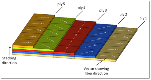
Use the Ply Directions subpanel to review the fiber direction of individual layers. You can choose from three different options to review (not all options are available for all supported user profiles).

ply based model: This option requires that the model has been defined in terms of plies (see an explanation in the notes section) or using HyperMesh ply and laminate entities. Click ply = and select one ply from the list to review.The fiber direction of the elements associated with the selected ply will be shown.
Ply based models consist of multiple plies representing the layers building a laminate. Additionally a stacking sequence needs to be defined to specify the order of how those layers are stacked. The big advantage of this type of modeling is that plies can span across elements. The modeling comes close to the way composites are manufactured.

composites_panel_plybasedmodel

zone based model: Select elems or props and enter the layer number to review. This review method works for either zone or ply based models.

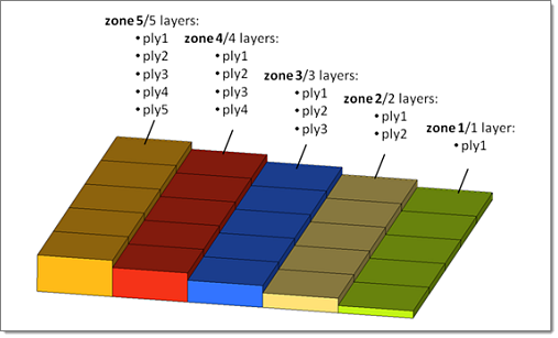
In a zone based model, each group of elements (zone) with the same number of layers requires its own property definition.

global zone based model: In case a model is defined using global ply names or ids, this method can be used for review purposes (e.g. ply name in Abaqus; global ply identification number in OptiStruct). Select elems or props, then click ply =. You will find all ply names or ids which are referred by your element selection; select one to review the fiber direction.

A global zone based model is similar to a zone based model. Ply ids or names are repeated in several property definitions, to highlight that these layers extend across two or more zones. In the example below, each zone requires its own property, but the name ply1 spans across all zones.

composites_panel_globalzonebasedmodel

Note:During review of the ply directions, size and color of the vectors can be adjusted, or join lines can be used to see connected lines between the elements.

For the Abaqus user profile, a Rebar Layer checkbox is available in the panel. It allows to review the fiber direction of each ‘rebar layer’ for GEOMETRY=CONSTANT. Review of other rebar options, such as ANGULAR or LIFT EQUATION are currently unsupported.

Panel Inputs

Input

Action

elems/props

Select elems or props for which to review ply directions. This selector is only available for the zone based composites models.

Rebar Layer

This option is only available in the Abaqus interface. In case the GEOMETRY=CONSTANT type is used, the rebar orientation angle can be reviewed for each individual layer. Review for the other types ANGULAR or LIFT EQUATION geometry (see Abaqus manual for details).

ply based model

Review the fiber directions for an entire ply definition. This option requires that the model has been defined in terms of plies (not all solvers support ply-based modeling) or  using HyperMesh ply and laminate entities. Click on the ply = selector and select one ply from the list to review. The fiber direction of the elements associated with the selected ply will be shown.

zone based model

Select elems or props and type in the layer number in ply = to review. This review method works for either zone- or ply- based models.

global zone based model

If a model is defined using global ply names or ids, this method can be used for review purposes (e.g. ply name in Abaqus; global ply identification number in OptiStruct).

Select elems or props, then click on the ply = field. You will find all ply names which are referred by your element selection. Select one to review the fiber direction

size

Enter a value in model units that specifies the length of the vectors for reviewing ply directions.  This only affects visualization, not any calculations.

join lines

Use this checkbox if you prefer to view connected lines instead of vectors.

color

Change the color of vectors or lines for review.

review

Review ply directions. Select elems or props and the ply = when dealing with a zone based or a global zone based model. For a ply based models you only need to select the ply of interest by clicking on the ply = field.

reset

Clear the ply direction review visualization vectors or lines.


See Also:

Alphabetical List of Panels