Engineering Solutions

Spotweld panel

Spotweld panel

Previous topic Next topic Expand/collapse all hidden text  

Spotweld panel

Previous topic Next topic JavaScript is required for expanding text JavaScript is required for the print function  

Use the Spotweld panel to create 1D elements to connect different parts.

Spotwelds can be created by using one of the following subpanels:

geometry

uses surface geometry obtained from CAD data

nodes

uses finite element model data

elems

internally remeshes the surrounding elements


Spotwelds can be created one at a time or in groups.

The 1-D element types you can create with the Spotweld panel include:

Elem type

Elem config

Screen display

External interfacing

bar2

60

A line between two nodes with BAR2 written at the centroid of the element.

Consult HyperMesh Entities and Solver Support section to determine which solvers support bar2 elements.

gap

70

A line between two nodes with GAP written at the centroid of the element.

Translates to CGAP element in OptiStruct, Nastran, or *GAP option in Abaqus.

plot

2

A line between two nodes.


rigid

5

A line between two nodes with the letter R written at the centroid of the element.

Translates to RBE2 in OptiStruct, Nastran, or *MPC in Abaqus

rod

61

A line between two nodes with ROD written at the centroid of the element.

Translates to CWELD/ CROD/ CTUBE/ CONROD in OptiStruct, Nastran, or a C1D2 element in Abaqus

spring

21

A line between two nodes with the letter K written at the centroid of the element.

Translates to CELAS1/ CELAS2/ CDAMP1/ CDAMP2/ CBUSH/ HMSPRING in OptiStruct, Nastran, or *SPRING in Abaqus

weld

3

A line between two nodes with the letter W written at the centroid of the element.

Translates to RBAR in OptiStruct, Nastran, or *MPC in Abaqus


Subpanels and Inputs


The Spotweld panel contains the following subpanels and command buttons:

hmtoggle_arrow1Using Geom

Surfs-surfs option


If more than two surfaces are within the search radius, spotweld elements are not created. To create welds in this situation, select a pair of surfaces at a time.

The local coordinate systems are oriented with the y axis located along the direction between the selected nodes.

Welds are placed in the current component.


surfs-lines option


For all surfs/elems Engineering Solutions attempts to weld together all surfs/elems found within the given search radius.  If more than two surfs/elems are found, Engineering Solutions attempts to weld all the layers together.  This option is present to allow for 2t and 3t welds.

For ind surfs/elems Engineering Solutions finds the first surf/elem (within tolerance) in each collector via a database lookup.

Note:This may not be the closest surf/elem; it is simply the first one that is found. Placing too many elems/surfs in each collector may lead to unexpected results.

The local coordinate systems are oriented with the y axis located along the direction between the selected nodes.


Panel Inputs

Input

Action

all surfs / ind surfs

all surfs: pick the surfaces in one step.

ind surfs: pick individual surfaces defining the independent and dependent regions.

surfs selector

Pick the independent surfaces.

If you select all surf, pick the two (or more) surfaces between which to create the element(s).

element config

The type of element to create.

weld location

The nodes or points located where you want to create spotwelds.

If you selected the lines option, each line is treated independently. This results in welds being located at the beginning and end of each line with the remainder of the welds being spaced evenly along the length of each individual line.

If you selected the line list option, all of the selected lines are combined head-to-tail in the order they were selected, and then treated as a single line. This results in only the beginning of the first line and the end of the last line having weld points, with the rest of the welds being spaced evenly along the length of the combined line.

property

Assign properties to the spotweld element(s).

Currently, bars, rods, springs, and gap elements are defined with a property ID.

search tolerance

The tolerance value to use to identify relevant surfaces between which to create the elements at the specified locations.

without systems / build systems

build systems: the local coordinate systems are built at each end of the spotweld element.

without systems: no systems are built.

spacing / density

Appears when lines-surfs option is selected.

density: indicate the number of spotweld elements to be created along the line.
spacing: specify a set distance between the spotweld elements to be created along the line.

offset options

You can either explicitly state the offset distance from each end on the line, or you can use the ½ spacing option.  The ½ spacing option determines the distance between two welds and sets the explicit offset to ½ of this distance.


hmtoggle_arrow1Using Nodes

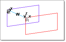
A weld built using build systems is illustrated below.

HM_Panels_bmp00396

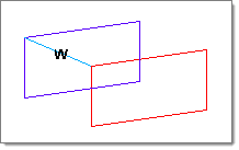
The illustration below shows a weld built using without systems.

HM_Panels_bmp00397


Comments


The local coordinate systems are oriented with the y axis located along the direction between the selected nodes.

The dependent node can be moved to create weld elements that are perpendicular to the surface formed by the elements attached to the independent node.  This relocation can occur either with or without pre-existing geometrical surfaces defining the "dependent surface."


Panel Inputs

Input

Action

indep node selector

Pick the independent node.

dep node selector

Pick the dependent node.

Engineering Solutions builds the element after you select the dependent node.

element config

The type of element to create.

move dep node

Activate the move dep node option if you want to move the dependent node along the surface in which it lies and create a spotweld normal to the independent surface.  If the quality of the resulting mesh due to the movement of the dependent node is not acceptable, click reject and activate the remesh dep region option to remesh the dependent region.  This option remeshes only the dependent region affected by the movement of the dependent node.

property

Assign properties to the spotweld element(s).

Currently, bars, rods, springs, and gap elements are defined with a property ID.

without systems / build systems

build systems: the local coordinate systems are built at each end of the spotweld element.
without systems: no systems are built.


hmtoggle_arrow1Using Elems

If more than two elements are within the search radius, spotweld elements are not created. To create welds in this situation, select a pair of elements at a time.

The local coordinate systems are oriented with the y axis located along the direction between the selected nodes.

Welds are placed in the current component.


Panel Inputs

Input

Action

all elems / ind elems

all elems: pick the elements in one step.
ind elems: pick individual elements defining the independent and dependent regions.

elems selector

Pick the elements.

element config

The type of element to create.

weld location

The nodes or points located where you want to create spotwelds.

property

Select the property collector to be assigned to the element.

Currently, bars, rods, springs, and gap elements are defined with a property ID.

search tolerance

Enter the tolerance value to use to identify relevant surfaces between which to create the elements at the specified locations.

without systems / build systems

build systems: the local coordinate systems are built at each end of the spotweld element.
without systems: no systems are built.

attach to shell elems

Create 1-D connection elements and attach them to neighboring shell elements by internally remeshing the surrounding elements.


hmtoggle_arrow1Switch Nodes

Panel Inputs

Input

Action

elems selector

Indicate the weld elements whose dependent and independent nodes you want to switch.


hmtoggle_arrow1Command Buttons

The following action buttons appear throughout the subpanels:

Input

Action

create

Creates the spotweld element.

reject

Reverts the most recent changes.

review

Displays the selected spotweld elements.

switch

Switches the selected elements.

return

Exits the panel.


See Also:

Spotweld Log file

Alphabetical List of Panels