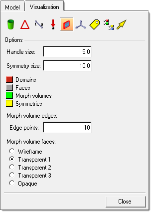
Local domains are represented by a single rectangle for 1D domains, two joined rectangles for 2D domains, a cube for 3D domains, four joined rectangles for general domains, and a line for edge domains. Local handles are orange if they are not dependent on other handles. Local handles are green, blue, or pink if they are dependent on other handles, the color indicating their level of dependency. The base size of all the handles in the model can be set on the morphing Visualization Controls tab accessed by using the Visualization Options icon  on the Visualization toolbar. The size given is used as the diameter for the independent local handles. You cannot edit the color of the handles nor the relative size between the dependent and independent handles. However, you can edit the color of the domains in the morphing Visualization Controls tab.
Local domains can be created individually by selecting nodes or elements in the create subpanel of the Domains panel. When local domains are created, HyperMorph automatically places local handles at the ends of all edge domains. These local handles are named local followed by a number. The placement of local handles depends on the type of domain created and the partitioning options, if partitioning is selected.
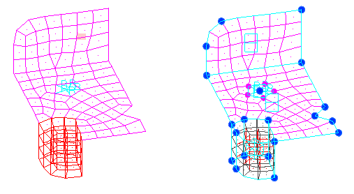
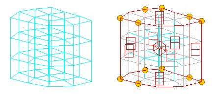
Example of a model with local domains and local handles with partitioning.
In the example above, the rigid elements have been placed in a 1D domain with the center node having an independent (orange) handle and the other nodes having dependent (green) handles. The shell elements have been placed in two 2D domains separated at the bend line due to partitioning. The solid elements have been placed in a 3D domain. Note that shell elements have been created on the faces of the 3D domain. These elements are placed in a component named ^morphface. Also note that 2D domains have been created on the faces of the 3D domain and that edge domains have been created on the edges of all the 2D domains. Finally, handles have been placed at the ends of all the edge domains.
1D Domains
Domains made up of 1D elements, such as bars and rigid elements, are called 1D domains. When automatically creating local 1D domains, 1D elements that share common nodes are grouped together into 1D domains. An independent local handle is placed at the centermost node of the 1D domain and dependent local handles are placed at every other node of the elements in the 1D domain. The independent handle is larger and orange, while the dependent handles are smaller and green. All the dependent handles in a given 1D domain are directly dependent on the independent handle. This dependency relationship means that moving the independent handle also results in moving the dependent handles the same amount in the same direction. This is done to preserve the unique relationship established for groups of 1D elements. Additionally, the bias factors for the dependent handles for a 1D domain are given an initial value of 3. All other handles in the model are given a biasing factor of 1. A higher biasing factor means that a given handle will have greater influence over the surrounding mesh than the others. The higher biasing factor given to dependent handles on 1D domains is intended to prevent mesh distortion when the 1D elements connect to nodes in 2D and 3D domains.
A rigid spider becomes a 1D domain
An independent local handle (orange) is placed at the centroid of the 1D domain and dependent
handles (green) are placed at each node. By moving the orange handle, the entire spider is
moved, maintaining the proper shape and connectivity for the rigid spider.
2D Domains
Domains made up of shell elements are called 2D domains. When automatically creating local 2D domains, shell elements that share common nodes are grouped together into 2D domains. If partitioning has been selected, these domains are subdivided into smaller domains along break angles and curvature changes according to the partitioning parameters. Edge domains are placed along the edges of the 2D domains and are also partitioned. Local handles are placed at the ends of all the edge domains. In general, the local handles are placed at the corners of the 2D domains and at other useful positions. The intent is to make it faster and easier for you to apply parametric changes to the model. Since you morph the model by moving handles, it helps to have handles already at the positions where you want them. HyperMorph tries to predict where the handles should be placed to reduce the amount of time it takes to prepare your model for morphing. If the handles or domains are not laid out in the positions where you want them to be, you can delete them, edit them, or create new ones. Also, even though the generated local handles are associated with the edge domains, they will influence the nodes in any domain that shares the node at which it is placed. This is true even if the handle is associated with the 2D domain. A handle associated with any domain will always influence the nodes in domains that it is touching. Note that it is possible to create a handle on a node that is not touching the domain to which it is associated. This allows you to place a handle outside of a domain, such as floating in space near the domain, and have it influence the nodes within its domain.
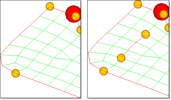
Two 2D domains with edge domains and handles
The model on the left shows the initial handle positions. The model on the right shows the addition of
four new handles. Handles can be placed anywhere, even at nodes not on the associated domain.
3D Domains
Domains made up of solid elements are called 3D domains. When automatically creating local 3D domains, solid elements that share common nodes are grouped together into 3D domains. Shell elements are created on the faces of each 3D domain and placed into a component called ^morphface. It is recommended that you do not delete or edit these elements nor rename or delete the ^morphface component. However, if you do, these elements and their 2D domains will be regenerated the next time you enter or exit a HyperMorph panel or the Delete panel. The shell elements on the face of each 3D domain are placed into a 2D domain that is then partitioned if the partitioning option is active. Edge elements are placed around each 2D domain and local handles are created at the ends of each edge domain. In cases where shell elements that are attached to the faces of solid elements are present in the model, HyperMorph will not create ^morphface elements coincident with the existing elements. The color of the ^morphface component can be changed on the morphing Visualization dialog accessed by using the Visualization Options icon on the Visualization toolbar. Note that the face elements in the ^morphface component will not be written out to any FEM formatted deck since the component name begins with a "^".
A block of solid elements is made into a 3D domain
The gray shell elements on the face of the 3D domain are the ^morphface
component. The ^morphface component has been partitioned into 2D domains.
Handles are created at the corners of the 2D domains.
Edge Domains
Domains made up of a list of nodes are called edge domains. When automatically creating local edge domains, edge domains are placed around the edges of all 2D domains. When you are selecting domains and are holding the mouse button down while placing the mouse over the icon of a 2D or 3D domain (or an element in the domain), HyperMesh will highlight both the domain icon and the surrounding edge domains. This makes it easier for you to tell which domain you are selecting. When you release the mouse button, only the icon for the domain remains highlighted.
Edge domains and 2D domains on the faces of 3D domains play an important function in determining the influences for the handles over a given domain. Nodes on edge domains will only move as a function of the handles touching the edge domain. No other handles will affect the nodes on the edges. Similarly, nodes in a 2D domain on the face of a 3D domain will only move as a function of the handles touching the 2D domain. This preserves the boundaries of 2D and 3D domains such that straight edges remain straight, flat surfaces remain flat, and curved edges retain their curvature. It allows you to move handles within a 2D or 3D domain without affecting the edges. If you do not want to have the boundaries of a domain preserved you can delete the edges for a given domain, or choose to create the domain as a general domain instead. Also, non-reflective symmetries allow the influences of handles to extend through edges and faces depending on the type of symmetry. For domains that have non-reflective symmetry types, the boundaries may not be preserved during morphing.
Examples of edge domains
Edge domains are placed around the edges of 2D domains. In the model at the right an edge domain
has been created inside a 2D domain. Note that when an edge domain is created, it is partitioned and
handles are placed at the ends and joints.
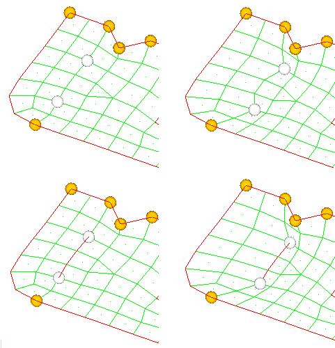
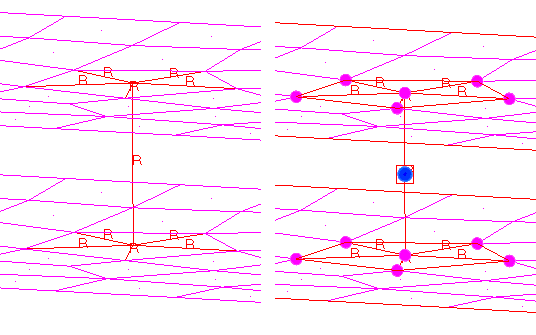
How edge domains affect morphing
In the top two frames two handles inside a 2D domain are created and moved. In the
bottom frames, two handles connected by an edge domain are created and moved.
Note that the edge domain remains straight, preserving the shape of the feature.
General Domains
General domains can be made up of any combination of 1D, 2D, and 3D elements. General domains are not automatically created when automatically generating local domains. Like all other domains, the elements within a single general domain must touch one another.
When a general domain is created, no 2D domains are created on the faces of any 3D elements and no edge domains are created either, thus no handles are created for the domain. However, general domains respect all neighboring edge domains and 2D domains and thus if you create 2D and edge domains for your general domains they will impose restrictions on handle influences for the general domain. Otherwise, handles on a general domain freely influence all of the nodes inside the general domain, allowing it to stretch and deform in an unbounded manner with morphing extending across differences in element type. General domains are very useful for realized connectors which are often represented as clusters of different element types. Another use is for meshes where precise changes are required for one section, where 1D, 2D, and 3D domains are used, but the rest of the mesh (where a general domain is used) can simply follow along.
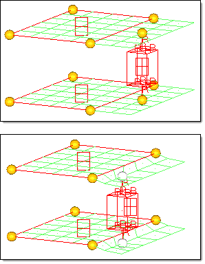
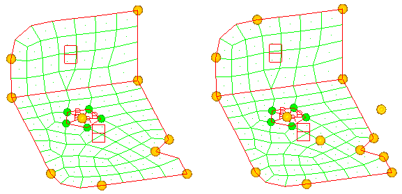
Example of interaction between a general domain and 2D domains
In the top frame, two 2D domains are created for parts of two shell meshes
and a general domain is creating from the remaining rigid, shell, and solid
elements. Two handles have been placed within the general domain at the
ends of the rigid spiders. In the bottom frame the two handles inside the
general domain are translated. Note how the shell elements in the general
domain morph, bounded only by the edge of the 2D domains with the other
edges free to follow the handles.


