|
»Click here to display Table of Contents«
|

Mesh Coarsening |

|

|

|

|
|
Mesh Coarsening |
|
|
|

|
|
»Click here to display Table of Contents«
|
Mesh Coarsening |
|
|
|
|
|
Mesh Coarsening |
|
|
|
|
An existing mesh may be finer and more complex than your simulation requires. This can result in the simulation, or other utilities that depend on existing elements, taking an unnecessarily long time to run, especially when your goal is to view real-time animations for NVH (Noise, Vibration, and Handling) or similar analyses.
In such cases, use the Coarsen Mesh tool to simplify the mesh by combining many small elements into a smaller number of larger ones.
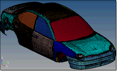
A model before coarsening (mesh size 30)
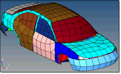
The same model after coarsening (mesh size 200)
When a mesh is coarsened like this, it is important to note that every node in the coarse mesh corresponds exactly to one of the nodes in the original mesh, although many nodes are removed, the ones that remain are still the same nodes from the original model. No locations or qualities are changed. Similarly, any nodes or points with special information (such as comments) in the 10th column of their deck will be preserved.
As the example above indicates, it is best to filter out components that are not relevant to your analysis. In this case, the wheels and suspension were removed from consideration.
This tool opens in a free-floating dialog.
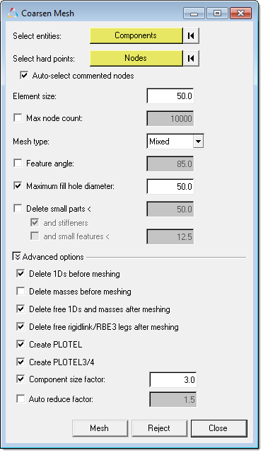
From this dialog, select the components that you wish to simplify, any hard points (such as those defining a hole or ridge) that must be preserved, a new element size, and a mesh type (Mixed or Trias-only). In both cases, you must click the selector twice, as if you were accessing its extended entity selection menu; however, the second click opens a temporary panel in the panel area. From this panel, select the desired components or nodes, and then click proceed to close the panel and return to the Coarsen Mesh dialog.
| • | Maximum Node Count prevents the coarsened mesh from exceeding a target number of nodes. This is an iterative process and will adjust the mesh size you specified accordingly. |
This option is helpful when you have large models and want to better control the size of the output for NVH models. The maximum node count will apply to all of the selected components. If you would like greater control of a specific component, coarsen that component separately.
| • | Feature angle eliminates and meshes over features with angles smaller than the specified value, while preserving features with angles greater than the specified value so that the mesh aligns with the feature line rather than allowing elements to cross over it. |
The coarsening process uses two stages; if the first stage fails on some elements, the second stage is run. The feature angle setting only applies to the second stage; it is irrelevant to the initial stage.
| • | Minimum fill hole diameter meshes over holes smaller than the specified value, but preserves holes that are at least the specified value. |
| • | Delete small parts (features & stiffeners) removes most features that become detached during the coarsening process, which are underneath the target input size that you specified. The entire feature must be within this limit. For example, a free bolt hole that is 3 units in diameter but 25 units in length will remain if this amount is less than 25. |
You can specify several options, which are accessible under Advanced options.
| • | Delete 1Ds before meshing Any 1D elements that are part of the input selection are considered for this operation. If those 1D elements are attached to a hard point or are part of a 1D path back to the 2D/3D structure, those elements are not deleted. Any other 1D elements that are part of the input selection are deleted. |
| • | Delete masses before meshing considers any 0D elements that are part of the input selection for this operation. If those 0D elements are attached to a hard point or are part of a 1D path back to the 2D/3D structure, then those elements are not deleted. Any other 1D elements that are part of the input selection are deleted. |
| • | Delete free 1Ds after meshing The coarsening operation itself includes making sure the relevant rigidlink/RBE3 elements are connected back to the structure accordingly. For this option rigidlink/RBE3 elements are considered free only if all legs are free after coarsening/reconnection is complete. |
| • | Delete free rigidlink/RBE3 legs after meshing deletes any free legs after coarsening and reconnection are complete. As mentioned above, a rigidlink/RBE3 element is only free if all legs are free for the purpose of this tool. |
| • | Create PLOTEL converts any remaining 1D elements that were part of the input selection to PLOTEL, once all of the above rules have been completed. This includes all legs of rigidlink/RBE3 elements. Every leg of these elements needs to be converted to a separate PLOTEL (for example, a 10 leg RBE3 will be 10 PLOTELs). |
| • | Create PLOTEL 3/4 converts all Tria and Quad elements to PLOTEL3 or PLOTEL4 element types configurations. This option is only available in the OptiStruct user profile. |
| • | Component size factor converts |
| • | Auto reduce factor converts |
Once you set the desired options, you can Mesh the selected components. If the results are not satisfactory, you can Reject the new coarse mesh, change the options, and try again.