|
»Click here to display Table of Contents«
|

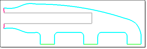
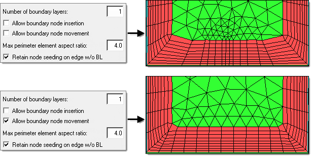
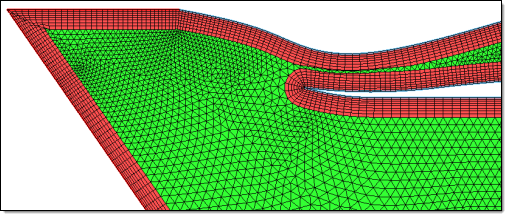
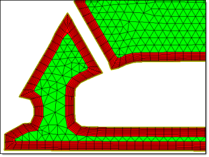
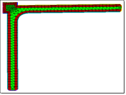
Meshing a 2D Planar Area with Boundary Layers |

|

|

|

|
|
Meshing a 2D Planar Area with Boundary Layers |
|
|
|

|