AcuSolve requires that you define all the exterior faces of every volume component. This is natural for a single volume domain having a boundary defined, for example, by a wall, an inlet and an outlet. You can use the path BCs > Faces to generate a ^faces component with all the boundary elements of your volume domain fluid, then use the path Mesh > Organize to move elements from ^faces to the corresponding surface components: for example, components named wall_fluid, inlet_fluid and outlet_fluid.
If you have two domains (for example, fluid1 and fluid2), then in addition to defining separate components with boundary elements for all the exterior boundary elements of components fluid1 and fluid2 (for example inlet, outlet, wall), you need to define two additional components that contain the remaining boundary elements (from ^faces) of each volume component fluid1 and fluid2. Call them inter_fluid1 and inter_fluid2 as follows, for example:
| • | inter_fluid1 contains all the element remaining in ^faces (obtained from volume fluid1) after you have moved the real exterior faces to the corresponding components, for example: inlet, outlet, wall. |
| • | inter_fluid2 contains all the element remaining in ^faces (obtained from volume fluid2) after you have moved the real exterior faces to the corresponding components, for example: inlet, outlet, wall. |
| Note: | Even though in this case inter_fluid1 and inter_fluid2 may appear to be the same because they both contain the interior faces that are the boundary between components fluid1 and fluid2, in fact they are different because they have been obtained from different sources (namely ^faces generated from component fluid1 and fluid2, respectively). If you inspect them, you will notice that the elements in inter_fluid1 have normals pointing to the inside of fluid1, whereas the elements in inter_fluid2 have normals pointing to the inside of fluid2. |
|
The above concepts are illustrated with an example:
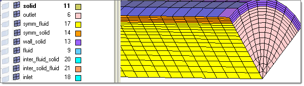
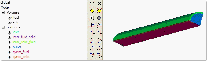
This model has two volume domains, named fluid and solid. They are shown below:
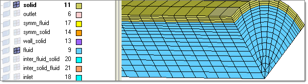
To generate all the boundary components as required by AcuSolve, you first extracted ^faces (using BCs > Faces) from the fluid volume component. Some elements from ^faces were moved (Mesh > Organize) to symm_fluid, some to inlet, some to outlet and the remaining are those in contact with the component solid. They are moved to component inter_fluid_solid. All of these components are shown below.
All of these component should define a closed volume; there should be no free edges. You can test this by using BCs > Check > Edges to find free edges. By selecting all the elements in the components displayed above, you will see a message as follows:

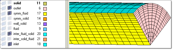
Similarly with the other volume component named solid in this example, you first extracted ^faces (using BCs > Faces) from the fluid volume component. Some elements from ^faces were moved (Mesh > Organize) to symm_solid, some to wall_solid and the remaining are those in contact with the component fluid. Those are moved to component inter_solid_fluid. All of these components are shown below:
Again, for this volume component named solid, the boundary components displayed above should define a closed volume; there should be no free edges. You can test this by using BCs > Check > Edges to find free edges. By selecting all the elements in the components displayed above, you will see a message as follows:
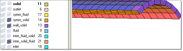
Before exporting the CFD model as a set of AcuSolve files (.arm, .inp and all the mesh files in subdirectory HYPERMESH.DIR), make sure that all the volume and surface components that define the CFD model are displayed as shown below:

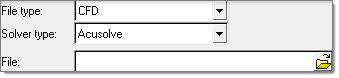
Then, using the Export tab, set the file type field to CFD, select AcuSolve in the Solver type field and browse to select the file.
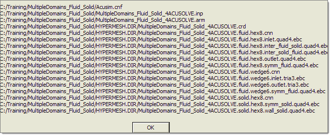
At the end of the export process, you will see a popup message window listing all the created files:
Using AcuConsole, you can import the CFD model created with Engineering Solutions by using the path File > Import. Select the .ARM file that you saved with Engineering Solutions and you will see the volumes and surfaces that you defined. This is shown below:
See Also:
Tips for CFD Solvers


