Engineering Solutions

NVH-1100: NVH Director Assembly

NVH-1100: NVH Director Assembly

Previous topic This is the last topic Expand/collapse all hidden text  

NVH-1100: NVH Director Assembly

Previous topic This is the last topic JavaScript is required for expanding text JavaScript is required for the print function  

The Assembly browser is an object oriented modeling environment where the fundamental entity is the module entity. A module is a HyperMesh entity used to represent subsystems of an assembly.

hmtoggle_plus1greyStep 1: Start NVH
1.Click the userProfile-24 icon on the Standard toolbar.  
2.Click Engineering Solutions > NVH from the User Profiles dialog.        
3.Click OK. A file save warning message displays informing you that the complete assembly database can only be saved in the XML format, as shown in step four of this tutorial.

nvh-1100-57

hmtoggle_plus1greyStep 2: Define Assembly Hierarchy
1.Click View > Assembly Browser.
2.From any view of the Assembly browser, right-click and select Create Module.
3.Enter a module name, and then click OK.  Repeat the process to create all root level modules for the assembly. Expand the assembly by clicking the ‘+’ box next to Module Model.
hmtoggle_plus1greyStep 3: Load an Assembly Definition XML file
1.From any view of the Assembly browser, right-click and select Import XML and Display or Import XML Only. The XML Import dialog opens.  
2.After naming the module, you need to import an .xml file. This should be an assembly database file that you exported from the NVH Director. Click the folderOpen-16 icon to navigate to a folder where the .xml file is located.
3.Select the file and click OK to load the file. The assembly information will be loaded into HyperWorks.
hmtoggle_plus1greyStep 4: Save an Assembly Definition XML file
1.To save the Assembly definitions in XML files, click the tabModuleFiles-24 icon.

nvh-1100-58

Note:The Preserve option saves an assembly XML file along with a set of nested subassembly files (similar to include files). The Merge option saves the assembly file with all subassembly files merged into it.

Subassembly files can be specified by clicking the ‘-‘ icon in the XML file path column. Navigate to the desired folder and specify a file name. Export of subassembly files can be controlled by checking/unchecking of the checkbox in the Export column.

Note:The Save XML option is enabled only in the File View to ensure that you are aware that the subassembly files are over-written.
hmtoggle_plus1greyStep 5: Define Module Representations

1.   Right-click any module and select Edit Representations. This opens the Edit Module tab, and the Representation sub-tab is shown.

2.   Select a module from the drop-down menu marked Module to select a different module. To create a representation for the selected module, right-click inside the top part of the Representation tab.      

nvh-1100-10

3. Select Add to add a representation.  

nvh-1100-35

4.On the newly created representation change the module description, if desired. A default description is created, which you can edit.

5.   After a representation has been added, use the Type field to select an appropriate Type and a file to be associated with the representation, and click Apply. Two convenient options can be selected during this step:

A file assigned to the root representation can optionally be auto-assigned to be a Display representation (PLOTFE type) simultaneously by checking the Assign file to Display representation checkbox.
A representation can be auto-selected to be the Display representation by checking the Set as Display, load and extract TagPoints checkbox. This will be followed by the file being imported into the 3D graphics window and TagPoints defined in the file extracted.

6.   Aside from file based representations, a templated Lumped Parameter (LP) representation can also be defined using the LP templates included in the NVH Director, or user created templates.  

nvh-1100-61

7.   Select one of the representations to be the active Display display-24 or Analysis analysis-24  representation by checking the appropriate radio buttons.

8.   Repeat the process by selecting another module through the drop-down box on the top right side.

9.   Once all representations are defined, click the Assembly tab to review the assembly hierarchy with active Display and Analysis representations.

hmtoggle_plus1greyStep 6: Import Display Representations

1.   From the Base View tabModuleRepresentation-24 of the Assembly browser, select the root Module Model.

2.   Right-click and select Import Display Rep to load the active Display models. Module representation include files specified as the display representation are loaded here.

hmtoggle_plus1greyStep 7: Manage TagPoints
1.To manage tagpoints, open the TagPoints tab of any module by right-clicking the module in the Assembly browser and then select Edit TagPoints.
2.To add a tagpoint, right-click inside the tagpoint list box, and select Extract All to extract tagpoints from the comments added to the 10th field of the grids in the loaded Display model.

nvh-1100-16

Tagpoints displayed in the 3D graphics area can be customized via the TagPoint Display tool setting. By default, tagpoints are indicated with a grey sphere along with the label. Other options are available using the pull-down menu.

nvh-1100-17

3.   Repeat the extraction process to complete tagpoint definitions of all modules.

hmtoggle_plus1greyStep 8: Prepare a Module for Assembly

In the previous two steps, you have assumed that the representation file is already in an FE entity ID range that would not cause conflicts with other modules in the assembly, and all necessary tagpoints already exist in the file as 10th field comments on the respective grid cards. However, these assumptions are not met in most practical applications. Necessary preparation work needs to be done to get the module representation files to a state that is ready for assembly. This section describes how to accomplish this task.    

1.To start the process of preparing a module, right-click the module and select Prepare Module to enter into the Prepare Module Mode. The abbreviated Module ID Summary dialog opens.

nvh-1100-78

In the Prepare Module Mode the HyperMesh database is first cleared to remove any potentially conflicting FE entities, and then the root representation file is loaded into HyperMesh. A module ID summary is then presented with all necessary information needed for you to determine if the IDs need to be renumbered, and what range they should be renumbered to.

This dialog shown below opens as a part of the Prepare Module action. It is split into two sections. The bottom section describes the finite element entity ID in the imported FE file. The top section provides a way to renumber the IDs, if necessary, into a range that is not in conflict with other modules in the assembly. The Proposed range is what the dialog has identified as one conflict free range, which can be modified based on options to the right. Action is a user specified operation to organize IDs into the Proposed range.

nvh-1100-40

Once an appropriate ID management action has been applied, NVH Director enters the Prepare Module Mode, and a Prepare Module tab opens up in the browser area with sub-tabs designed to help you perform many functions, such as:

Add spider: Help add spiders to a round hole. Select a type, dofs, pick center (RBE3 only) and edge nodes, and then click Create.
Add PLOTEL: Helps you with PLOTEL display elements.
Edit systems: Help relocate or orient the module by modifying the reference local coordinate system. This opens the Systems panel to edit existing systems.    
Orient and position: Help translate and rotate FE entities. Input values in the appropriate input boxes and push one of the buttons below to perform the function.
Assign damping: Help fill GE field of MAT1 cards. Enter a damping value in the input box and click All or Select to apply the damping values to all or selected material cards.
Composite Response: Help define a new response point by relating its motion to existing tagpoints in the model. The most common example is to define a steering wheel nibble response using tagpoints at 6 o’clock and 12 o’clock on the steering wheel.                      

nvh-1100-72

In addition, a number of functionalities on the TagPoints tab of the Edit Module are enabled for you to manually add tagpoints and assign them to grids in the module. Lock ID’s provide you with a means to maintain the ID’s of tagpoints without getting renumbered by locking them. This prevents accidental renumbering of tagpoints. Lock ID’s have a higher preference than the sub ranging utility. If ID’s are locked for tagpoints, then sub ranging will not renumber those locked ID’s in prepare module mode. This utility can lock the ID’s of existing tagpoints using edit tagpoints or it can lock the tag ID while creating it using the create tagpoint utility.

nvh-1100-41

A tagpoint mapping tool is also available in the Prepare Module tab via the tagpointMapping-24 icon. The mapping tool is able to reconcile in bulk the current tagpoint definition in the assembly database with what is in the root module file. You can also create new tagpoints by reading a .csv file that contains hard point coordinate and label information.

nvh-1100-42

2.Once you are finished preparing the module, you can prepare another one from the Assembly browser, or select to exit the Prepare Module Mode by clicking X on the Prepare Module tab.

You will be prompted with four representation file save options with information on ID renumbering. Yes: The root representation file is to be saved, in this case, intra and inter ID conflict flag will be set to Yes. No: The root representation file is not to be saved, in this case, intra and inter ID conflict flag will be set to No. Cancel: The exit Prepare Module Mode action is aborted. No, but VALIDATE: In this case there is no change to the file and no need to save the file, but intra and inter ID conflict flag will be set to yes.

nvh-1100-44

3.Once all of the modules have been prepared, you can review the assembly ID ranges and conflict setting from the Id View of the Assembly browser.

nvh-1100-45

At the individual module level, the ID tab of the Edit Module will also be populated.

nvh-1100-46

It is also possible to view mass and damping information using the Property View in the Assembly browser.

nvh-1100-62

hmtoggle_plus1greyStep 9: Define Connections Between Modules

1.   Click the connectionCreateInteractive-24 icon to launch the connection Interactive Create tool.  

nvh-1100-70

2.   Connections can be created between modules to be connected either by selecting tagpoints from the list box in the dialog, or by picking tagpoints. Hint: Pick and drag on the left hand side of the tags to ease selection off the screen after clicking the entityTags-24 icon. You can also provide a description for the connector created, specify an owning module, a local coordinate system, connector location for the center of motion, and a collector for the connector created. Force ID's for connectors gives you an option to define the numbering pattern to a connector, so that the connection elements created by realization of those connectors fall in the defined numbering pattern. ID's are forced to connector elements and properties after realizing them. 

3.   Connections can also be created using the Auto Create tool, which can be invoked by clicking the connectionCreateAutomatic-24 icon. Two automated creation approaches are available: auto creation by Proximity or by Tagpoint Matching.

nvh-1100-71

4.   To review the connections that were created, click View > Connector Browser.

The Connector browser is divided into two browser panes. The top pane is the Module Pane, where connected modules are listed. You can view connections attaching to modules using typical browser functions, such as Show/Hide/Isolate.

nvh-1100-73

The lower pane is the Connector Pane, where individual connections are listed.

nvh-1100-74

The following connection views are available from the Connector Pane.  

Connectivity View tabConnectorsConnectivity-24 : Columns in this view focus on connectivity related details. Of particular importance are the following columns:

nvh-1100-75

PointA/PointB: These two columns show the two tagpoints on two modules that are being connected for each connection. The same order (PointA first and PointB second) is used when generating connection FE entities during connector realization. PointA/PointB may be shown with two incomplete status indications (in square brackets): [N/A] indicates that the tagpoint exists in the assembly database, but is not available in the HyperMesh session (not imported.) [Undefined]  indicates that the tagpoint does not exist in the current assembly database, which means the tagpoint is either deleted or the sub .xml file it travels with is not imported in the session.

Owning module: This column indicates which module owns the particular connection. The owning module is always the module on the PointA side of the connection. The connection definition and properties always travel with or organized under their owning modules when sub .xml files are written.

Distance: This column shows the distance between PointA and PointB. It can be used as a metric for checking the validity of the connection. Connections spanning large distances are potentially connected by mistake. Some NVH engineers prefer to keep all connections at zero length due to fear that non-zero length springs may introduce unintended dynamic motion, which is a valid concern if celas type spring elements are used during connector realization. When cbush type spring and rbe2 type rigid elements are used, this is the case for all current NVH Director supported realization types, correct dynamic motion is ensured by element formulation, and there is no longer a need to maintain zero connection length.

Switch nodes: This column shows if there is a need to switch the order by which PointA and PointB are used in generating rbe2 rigid elements during connector realization. This need is driven solely by dependency considerations of the connected points, since a point that is already dependent cannot be made the dependent point again in the connection element definition. Four possible states of this column are possible. No: If PointA is independent, regardless of the dependency of PointB. Yes: If PointA is dependent, but PointB is independent, in which case PointB will be made the independent point in realizations involving rbe2. Unresolvable: This happens when both PointA and PointB are already dependent, in which case a realization involving rbe2 is not possible, and the connection will fail to realize. Unknown: If PointA’s dependency status is unknown or if PointA is dependent and PointB’s dependency status is unknown.

Forced ID: Force ID's for connectors gives you an option to define the numbering pattern to a connector, so that the connection elements created by realization of those connectors fall in the defined numbering pattern.  

Property View tabConnectorsProperties-24: Columns in this view focus on connection property types defined, local coordinate systems used and property set that is active.

nvh-1100-76

Location View tabConnectorsLocation-24 : Columns in this view focus on the location definition.

nvh-1100-77

5.   To review unattached modules, go to the Assembly browser and select Find Unattached Modules. This action removes all modules attached by connections and provides a good way check if all components shown in the 3D graphics window are intentionally unattached.

6. Similarly, select Find Unattached TagPoints to see if some TagPoints are unattached by accident.

hmtoggle_plus1greyStep 10: Define Connection Information and Properties

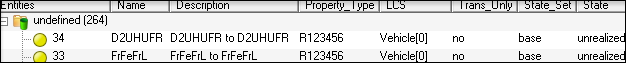
1.   Connection properties can be defined by first selecting a connector, right-click, and select Edit Connection. This opens the General tab of the Connection Manager, where you can edit the connector’s general information including Name, Description and Owning module.

2.  Click Update to save the changes. A connection location type can be defined by selecting one of the options from the pull-down menu: Point A, Point B, Midpoint, or a CustomLocation. When CustomLocation is selected, the location can be defined either by specifying a specific coordinate, or by mapping it to a Hardpoint location.

nvh-1100-32

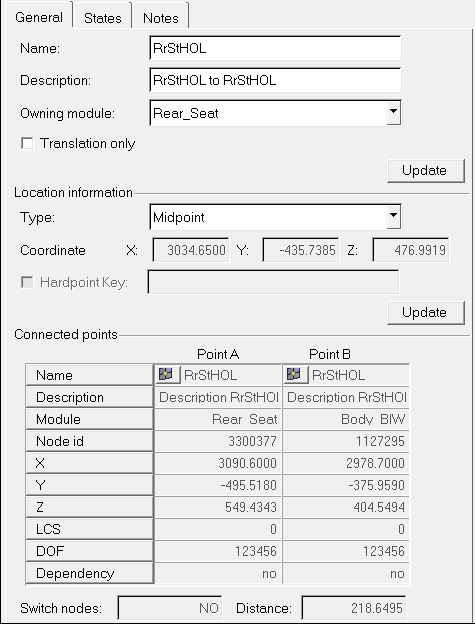
3.   Click Update to save the changes.

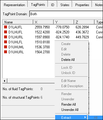
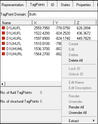
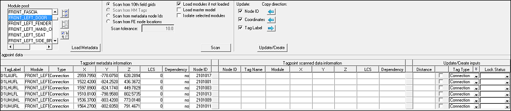
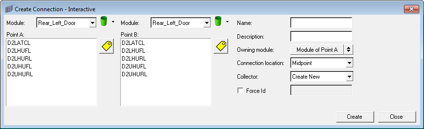
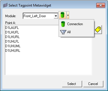
Information related to Connected Points, and distance between them, is displayed in the next section. You can modify any connecting tagpoint by clicking the entityNodes-24 icon next to its label, which opens the Tagpoint Selection tool. You can then select a module first in the Module pull-down list, select a tagpoint owned by the module, or click the entityTags-24 icon and pick a tagpoing on the screen in the 3D graphics window, and then click Select. The tagpoint list can be further filtered by clicking the entityConnectors-24 icon and selecting one of the tagpoint types: Response, Connection, Input, Plot, or All (default).

nvh-1100-48

When checked, the Switch Nodes checkbox allows you to change the independent node from Point A to Point B, based on their dependency status, to avoid an already dependent node being specified as dependent again when the connection is realized into new rigid elements. Connection properties are defined in the States tab of the Connection Manager.

nvh-1100-49

The first step in defining connection properties is to select a State Set. State Set is designed to capture a unique hardware part with its own set of connection properties. For example, hydromount vs. a base rubber part. By default, a base State Set is already created and assigned to the connector. Therefore, unless there is a need for multiple sets of properties, the default base State Set selection does not need to be changed.

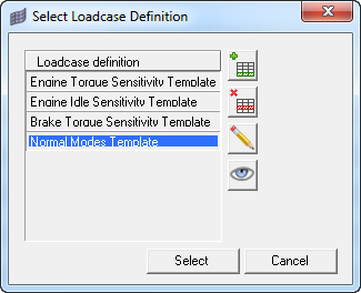
4.   To select another State Set click the Edit button. This opens the Select State Set dialog.

nvh-1100-50

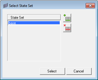
State Sets can be added by clicking the tableAppendRow-24 icon, or deleted by clicking the tableDeleteSelected-24 icon. You can double-click a State Set to edit its name, and click Select to finalize the selection.

The second step in defining connection properties is to select a LCS (local coordinate system) for the properties to be defined in the next step.

nvh-1100-52

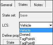
As seen in the screenshot above, four options are available in specifying coordinate systems used by any element generated during connection realization:

Vehicle – ‘0’ or the basic coordinate system is used.
Owned – This option allows you to create a custom LCS by clicking Edit.
TagPointA – Local coordinate system specified as the output Displacement Coordinate System on the grid card associated when TagPointA is used.
TagPointB – Local coordinate system specified as the output Displacement Coordinate System on the grid card associated when TagPointB is used.

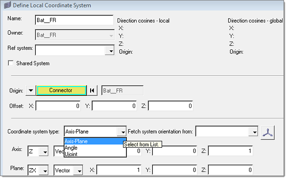
When the Owned local coordinate system is selected, a local coordinate system managed in the assembly can be created using the Define Local Coordinate System dialog. Three types of coordinate systems can be defined:

Axis-Plane – Two vectors are required to define this system. A vector can either be specified in direction cosines, or by selecting two tagpoints.
Angle – Any combinations of angle rotations around the reference axes can be used to define this system.
Ujoint – The Ujoint coordinate systems is defined by selecting two tagpoints on the input shaft and two tagpoints on the output shaft. A homo-kenetic coordinate system will then be created to properly describe motion transfer of Ujoints from the input to the output shafts.

define_lcs

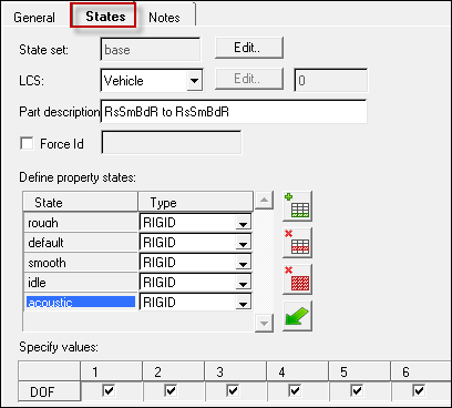
The last step in defining connection properties is to define property states.

define_property_states

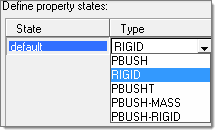
As seen in the screenshot above, five options are available in specifying property states:

PBUSH – A CBUSH element is generated during connection realization. The PBUSH card allows you to specify K (stiffness), B (viscous damping), GE (material damping), M (mass and moment of Inertia), and RIGID (checkboxes for rigidly connected dofs.) Note: The M and RIGID fields are not supported in the Nastran profile, and are ignored.
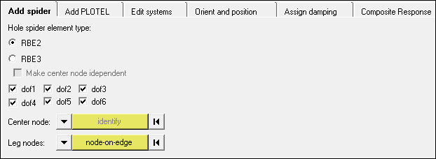
RIGID – A RBE2 element with dofs specified in checked boxes is generated during connection realization.
PBUSHT – A CBUSH element is generated during connection realization. In addition to the PBUSH card that specifies the base properties, a PBUSHT card allows you to specify frequency tables for K, B, and GE.
PBUSH-MASS – A CBUSH element with two COMN2 elements at its Point A and Point B are generated during connection realization. Note: This type is designed to be used in the Nastran profile where the M fields for PBUSH are not supported by the Nastran solver.
PBUSH-RIGID – A CBUSH element with a parallel RBE2 element are generated during connection realization. Note: This type is designed to be used in the Nastran profile where the RIGID checkboxes for PBUSH are not supported by the Nastran solver.

5.    Click Apply to save each property state definition. Property states can also be imported using the Import From File option by clicking the fileImport-24 icon. The Import States dialog opens.  

nvh-1100-53

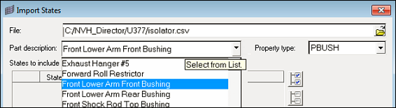
6.   Browse and select a connection property template file, select a connection property set, and click Import to load the property states.

7.    Repeat the above process for all connections to complete property definition.

hmtoggle_plus1greyStep 11: Manage Analysis

An Analysis is a collection of module, connection and loadcase selections that completely specifies the assembly definition for a particular simulation event. The Analysis Manager is invoked by clicking the analysisManager-24 icon.      

1.   To add an analysis by extracting active module and connection settings, click the tableAppendColumnExtract-24  icon. To add an analysis by copying module and connection settings from the selected analysis, click thetableDuplicateColumn-24 icon. To add a blank analysis, click the tableAppendColumn-24 icon.      

The top section of the Analysis Manager is used to define analysis, which is further divided into parts. The first part is for module representation and state selection, the second is for connection state selection and the third part is for loadcase definition.  

2.To define module representations, select the representation via the list individually, or globally all representations by type via the right-click context menu.
3.To define connection state, pick a State label.  
4.To define template load case, click the ‘…’ icon to invoke the Select Loadcase Definition dialog.

nvh-1100-55

5.Highlight an existing definition or add a new one by clicking the tableAppendRow-24 icon.

The lower section of the Analysis Manager is used to apply the module representation and state selections to the modules in the assembly, realize connections to states defined into corresponding FE entities and render the defined loadcase into solver cards. Once an analysis has been applied, the Job options section is enabled.  

6.If the Create job option is selected, you can select a Job folder and click Create Job, which opens the Job Submission dialog, allowing you to select a number of solver related options. You can select the server, local or HWUL for solving the runs. Clicking Submit Job creates the analysis job and submits it to the target solver for analysis. Subsequently, the job will be accessible through the Job Manager.    
7.If the Export deck option is selected, click Export to save a solver deck for manual submission to the targeted solver for analysis. All analysis information is saved in the assembly .xml file and retrieved when the file is loaded back.


See Also:

NVH Assembly Overview