|
»Click here to display Table of Contents«
|

Orientation Review |

|

|

|

|
|
Orientation Review |
|
|

|

|
|
»Click here to display Table of Contents«
|
Orientation Review |
|
|
|
|
|
Orientation Review |
|
|
|
|
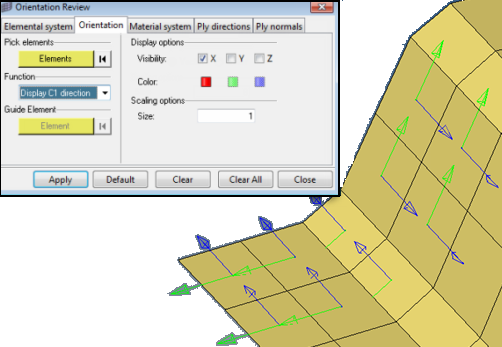
In the Aerospace user profile, Orientation Review is available via the Tools and Aerospace menus.
Use the Orientation Review tool to display/review and modify frequently used coordinate systems used in CAE analysis.
The following tabs can be accessed in the dialog:
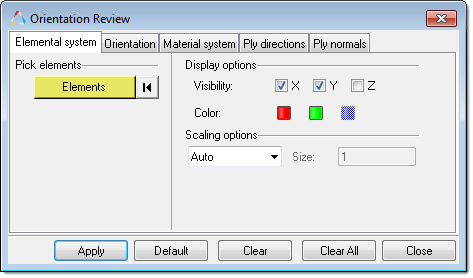
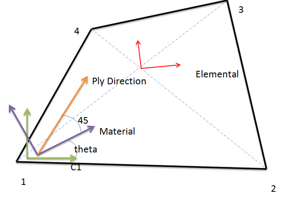
In the Elemental system tab you can select 1D, 2D, or 3D elements and display the coordinate system. Elemental systems are dependent on the solver type. For example, for Nastran and for quad elements the X axis is determined using the bisector of the diagonal line. Select the element and click Apply to show the system display. The mode element can be added and the display can be super imposed. Clicking Clear removes the information that you added, and clicking Clear All removes the system.
|
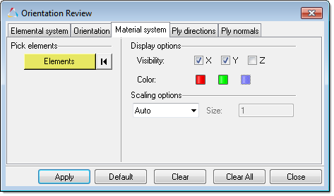
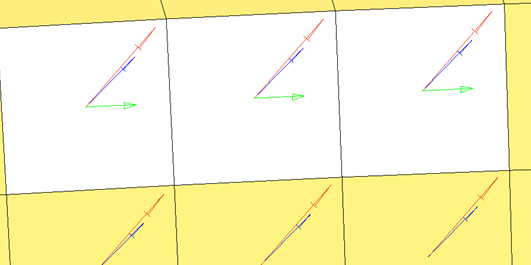
By default the material system aligns with the C1 direction of the element edge. C1 is the direction from node 1 to node 2 of the element. You can super impose the elemental system on the same plot of the material system.
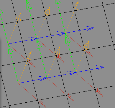
The blue and green arrows represent the elemental system (x and y) and the red and brown arrows represent the material system (x and y) |
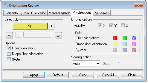
During CAD import of the composite data, each ply is associated with one or a separate system (one system for several plies or a system for each ply). You can select a ply and review its system. This is important to align the element normal to match the ply normal, or correct the ply angles if the normals are in the opposite direction. There are three function options:
The green arrows show the material X direction. The blue arrow shows the ply 5 fiber direction without drape. The red arrows shows ply 5 fiber direction with drape. |
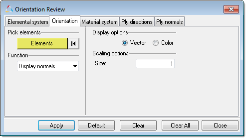
In the Orientation tab you can display and correct element orientation. Element orientation is determined by the order of the nodes in the element connectivity. This is sometimes referred to as C1, C2, C3, or element local system.
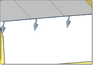
Display normal and reverse normal 2D elements
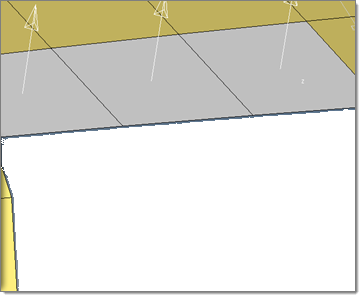
Reverse normals. The element already selected during the display normal will be reversed.
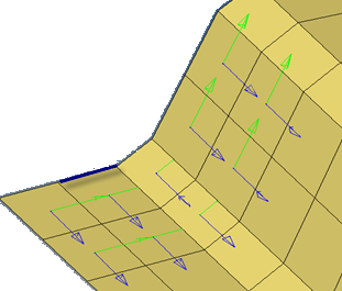
C1, C2, C3 direction: This displays the element orientation of the nodes. C1 is the direction from node 1 to node 2 using the element connectivity order.
Resequence nodes: align C1 direction of 2D quad elements. Using the display C1 direction, some of the elements may not be aligned, as shown in the previous image. Select a guide element as the reference element and the rest of the element node connectivity will be changed to align the C1 direction.
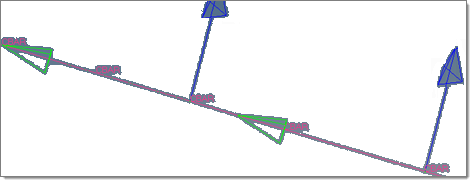
Reverse 1D element direction. This function reverses the X direction (node 1 to node 2) of a 1D element. This image shows before reversing the elements.
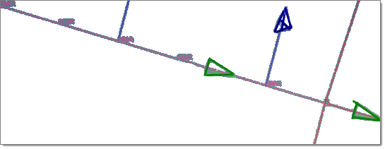
After reversing the elements When the function is set to Align N1-N2 dir., you must select a selection method.
The orientation of the rest of the elements will be determined based on the orientation or direction of the selected entity.
|
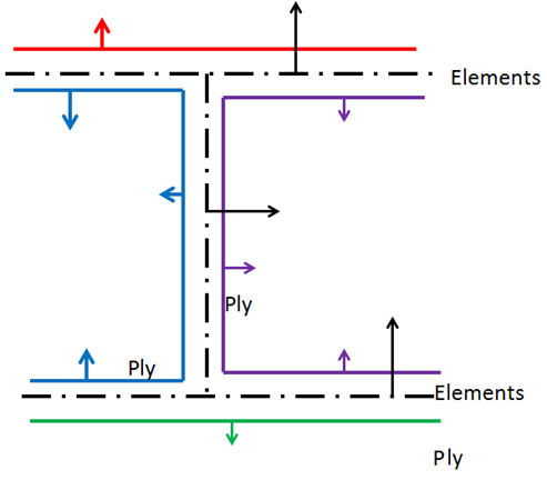
CAD based ply angles and orientation are transformed with respect to the element material system for analysis solvers. Most of the time you can correct the element normal to match the ply normal from the CAD. There are times when it is not possible to change the element normal to match the ply normal, as shown in the diagram below. In these cases, you need to change the ply angles with respect to the element normal without changing the element normal. For example, a +45 degree ply will become a -45 degree ply if the element normal and ply normal are in opposite directions.
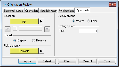
The ply normal does not match the element normal The Ply normals tab lets you indicate which ply angles need to be reversed for which elements when they do not match the ply normal.
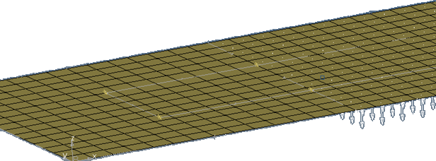
Perform the following steps:
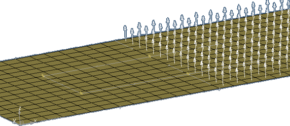
The element normal for the ply is now reversed. Note that the actual element normal is not changed. The software takes a note (sets a flag internally) for a particular ply, and the angle needs to be reversed for that element, instead of reversing the normal. This is reflected in the solver data. |