Use the Part Replacement tool replace a part with an existing part in your model or a part from an external file. During the replace operation, you can define the tolerance that determines how the new part attaches to your model. If you change the tolerance, you can click Preview in the browser and examine the effect of the change before accepting it.
In Ansys, surface elements, if created on the component that is being replaced, will not be remeshed to match the new mesh. Also, for edge to edge contacts on shell components, if those shell components are being replaced, then the contact edge surfaces will not be updated.
Only available for LS-DYNA, OptiStruct, Nastran, PAM-CRASH2G, Abaqus, Ansys, and all Engineering Solutions user profiles.
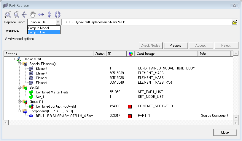
| 1. | From the Model browser, right-click on a component and select Replace from the context menu. The Part-Replace dialog opens, and lists all possible entities affected by the part replacement. |
| 2. | In the Replace using field, identify the input file that contains the target, replacement part. |
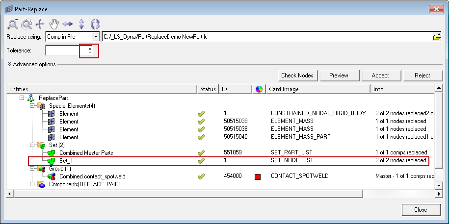
In the following example, Comp in File is selected as well as an LS-DYNA input file that contains the target part.
| 3. | Under Advanced options, select advanced part replacement options. |
| • | To capture all operations related to the part replacement, select Write log files and specify the log file to create. |
| • | To update node sets and/or boundary conditions when replacing a mesh with a very fine mesh, select Merge Nodes on target component boundary and Box Approach for Node Sets. Only available for OptiStruct, Nastran, Ansys, and Abaqus. |
| • | To copy the element type card from the source to the component that is being replaced, select the Assign source component element type to target component element type checkbox. Only available in the Ansys user profile. |
| 4. | In the Tolerance field, enter a tolerance to search for reconnection. The default tolerance is set at 0.01. Once you specify a tolerance, click Preview to show the status of the reconnection of the target part to the model. The tolerance value is used to look for closest nodes and elements to re-establish the connections and other references between the target part and the model.
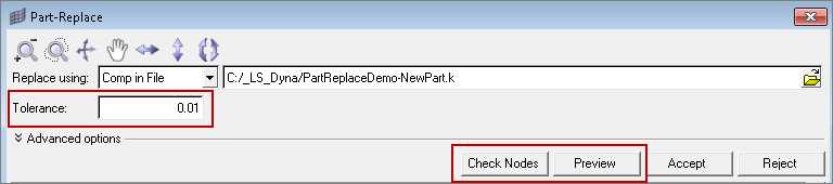
|
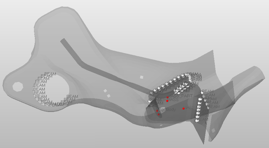
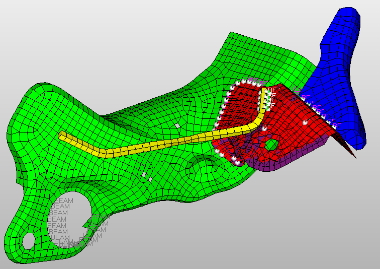
| 5. | To display connections, click Check Nodes. Connections are displayed in the Status column and in the graphics area.
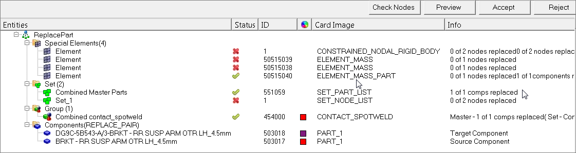
|
In the graphics area, green connections are highlighted white and red connections are highlighted red.
| 6. | Adjust the tolerance for the target part as needed, then click Preview to see the status. |
In the example below, the tolerance is changed to 5, and all of the connections are re-established.
| 7. | After adjusting the tolerance, click Accept. The source part is deleted and the connection of the new part to the model is accepted. |
Note: If the source part is connected by meshless welds, clicking Reject does not restore the model and welds to their original state prior to the part-replace operation.


