This tab displays in the tab area when you complete the Penetration panel and run an initial check. Use it to view the results of the check and make adjustments.
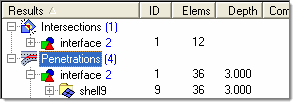
Penetrations and intersections display in a tree view, grouped by component (regardless of how you selected entities in the penetration panel).
Tab Usage
Once the penetration tab displays, you can freely exit the Penetration panel if need be and still retain (and work with) the penetration check results via the Penetration tab.
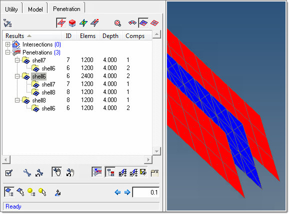
The tree view in this tab groups penetrations and intersections by component, even though it actually checks elements for penetration. Each component displays as a "parent" folder in the tree view, and — when expanded — displays the number of element penetration interactions that it contains and the components that it penetrates (which are listed as children within the comp’s folder). In the screenshot above, shell7, shell6, and shell8 display as parent entries, but each also has "children" nested within it in the tree. For example, the parent entry for shell6 displays shell7 and shell8 as children of it, because elements in shell6 penetrate elements in both shell7 and shell8. Shell6 has 2400 such interactions: 1200 interactions with shell7 and 1200 more with shell8.
| Note: | This does not mean that shell6 contains 1200 elements that penetrate something; rather, it means that there are a total of 1200 interactions involving shell6’s elements. In this example the three shells form a three-layer laminate, and each layer is thick enough to penetrate its adjacent later (but not beyond). Shell6 is the internal/middle layer and consists of 960 tria elements, while shell7 and shell8 (the two outer layers) each consist of 240 quad elements. As such, each of shell6’s 960 elements produces an interaction with one element in each of the outer layers — so the total number of element interactions between shell6 and shell7 is 1200 (960 interacting elements in shell6 and 240 in shell7). Shell6 also interacts with shell8 in exactly the same way — producing another 1200 interactions — for a total of 2400 interactions directly related to shell6, even though shell6 contains only 960 elements. |
|
In addition to the number of element interactions, each component’s entry also lists the depth of penetration (not valid for intersections) and the total number of other components that it penetrates or intersects with.
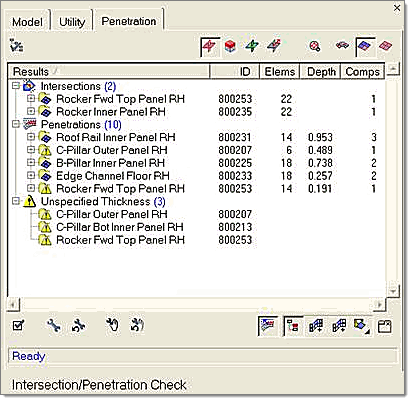
Penetration depth checking is completely dependant on element thickness. For this reason, any components with zero thickness display with a warning icon: a yellow triangle with an exclamation mark (!) on it. Such components are also repeated in a new branch at the end of the tree, grouped under the heading Unspecified Thickness.
Clicking one of the components in the tree control highlights the penetrating elements of both that component and the other components that it interacts with.
Button controls
The Penetration tab includes controls to modify the view in the graphics area, as well as to modify the penetration itself and to re-run checks with modified criteria. These buttons even allow you to perform fixes by moving elements based on their penetration vectors and depth.
These buttons are arranged into three toolbars:
This toolbar displays along the top of the Penetration tab.
Button
|
Action
|

|
Options: opens the Options window, which controls options for the penetration checking and fixing tools.
|

|
View Mode: Highlight Failed Elements. This default option highlights any elements that caused penetration or intersection when you select a component in the tree view.
|

|
View Mode: Review Failed Elements. This option makes all elements transparent (wireframe) except for the interacting elements of the component that you click in the tree view—those elements display in solid color.
|

|
View Mode: Penetration Contour. This option displays a color gradient of the penetrating elements in the selected component, which indicates the severity (degree) of penetration for the interacting elements. This mode is not available for intersections because their depth cannot be determined.
|

|
View Mode: Penetration Vectors. This mode display individual vectors for each penetrating element in the component that you click in the tree control. These vectors indicate the direction and depth of penetration for both the selected comp and its interacting comps. This mode is not available for intersections because their depth cannot be determined.
|

|
Fit View to Failed Elements: Click this button always fit the failed elements to the display. In large models, this can be very helpful in finding and viewing small areas of minor penetration. Note that this is a "mode" button, not a command button; while it’s active, the view automatically fits to the penetrating elements of any component that you click in the tree list. Click the button again to deactivate this "fit" mode.
|

|
Mask controls: Display all elements. This button unmasks all elements in the model (but not other masked entities such as model geometry).
|

|
Mask controls: Interacting Components. This button masks everything in the model except for components with penetrations or intersections. Note that this only applies to comps for which you have run the current penetration check; other comps may be interacting, but if you have not run a check on them they do not appear as interacting, and they will be masked.
|

|
Mask controls: Display Only Failed Elements. This button masks everything in the model (including the interacting components) except for the specific elements that penetrate or intersect.
|
|
This toolbar displays along the bottom of the Penetration tab.
Button
|
Action
|

|
Recheck: use this button to re-run the check on exactly the same entities. You can even make adjustments in the Penetration tab such as changing the thickness adjustment, and then re-run the check. However, you cannot run a re-check if you change your selection of elements/comps/groups.
|

|
Fix controls: Automatic Intersection/Penetration Fix. Click this button to attempt to automatically fix the intersections or penetrations, based on the settings found in the Options window. The fix is performed on the component that you select (highlight) in the tree view, as well as any interacting components that fall within its folder in the tree view. Fixing a parent component automatically also fixes each of its child comps. You can even perform a fix on the entire "intersections" or "penetrations" group.
|

|
Fix controls: Undo Automatic Fix. If the results of the automatic fix are unacceptable, click this button to undo them. You can undo fixes on a per-component basis, regardless of the order in which the fixes were performed, by clicking a "fixed" comp in the tree view and then undoing its fix. Undoing the fix on a parent also undoes the fixes of its children.
|

|
Fix controls: Show Manual Fix Toolbar. This button toggles an additional toolbar on and off. The extra toolbar contains tools used to perform manual, rather than automatic, penetration fixes.
| Note: | manual fixes only function at the child level on the tree. (You cannot perform manual fixes on a parent). |
|

|
Fix controls: Undo Manual Fix. Click this button to discard and undo every manual fix performed since you first began manually editing the mesh. Notice that this does not necessarily restore the mesh to its original state when you loaded the model! For example, if you performed an automatic fix, and then performed additional manual fixes, undoing the manual fixes would restore the affected mesh to the point at which you began the manual fixes — thus retaining the changes already made by the automatic fix.
|

|
Display Depenetration Vector: when you highlight a child (end-level) entry in the tree control and this button is active, an estimated vector is displayed along which the penetrating elements could be moved in order to reduce or eliminate penetration. This vector is the inverted average of all penetration vectors for the highlighted component, so it may not be ideal in the case of a complex penetration.
|

|
Selection: Only on Child Component. This modal button affects what can/will be saved when you click the save penetration data button described below. When depressed, only the entities in the bottom-level of a tree branch can be saved; otherwise you can save the entities in an entire branch
|

|
Selection: Add Adjacent Elements on Face. Clicking this button adds every element directly adjacent to the currently highlighted ones to the selection so that you can save an expanded selection; in other words, it adds a single row of additional elements:
Note, however, that the addition can be restricted by the feature angle setting in the Options panel.
To de-select these extra elements and return to the original selection, click another entry in the tree and then click the original entry again.
|

|
Selection: Add Attached Elements on Face. Clicking this button adds every element directly attached to the currently highlighted ones to the selection, so that you can save an expanded selection. This can even select elements of an adjacent component, but is restricted by the feature angle setting in the Options panel:
To de-select these extra elements and return to the original selection, click another entry in the tree and then click the original entry again.
|

|
Save penetration data: click this button to save penetration entities to the user mark. Right-click (or click the bottom-right corner) to select the type of entity saved:
|
|
 | Save Failed Elements: highlighted elements are saved to the user mark, so that you can recall them later in other panels (such as the translate panel). |
|
|
 | Save Penetrating Nodes: the nodes of highlighted elements are saved to the user mark, so that you can recall them later in other panels. This might not save all of an element’s nodes, just the ones that penetrate another element. |
|
|
 | Save Penetrating Vectors: the vectors of highlighted elements’ nodes are saved to the user mark, so that you can recall them later in other panels. |
|
|
This toolbar displays along the bottom of the Penetration tab, but only when the show manual fix toolbar button in the second toolbar is active.
Button
|
Action
|

|
Select Elements By Tree: When this mode is active, clicking the lowest-level component in the tree structure selects all of its failed elements.
|

|
Select Elements Manually: When this mode is active, you can click each desired element belonging to the lowest-level component in the tree. This includes the ability to select non-failed elements or a sub-set of the failed ones.
|

|
Select Nodes By Tree: When this mode is active, clicking the lowest-level component in the tree structure selects all of the penetrating nodes in its failed elements. This differs from Select Elements By Tree in that individual nodes can be moved to fix a penetration (thus changing the shape of a failed element) instead of moving entire elements.
|

|
Select Nodes Manually: When this mode is active, you can click each desired node belonging to the lowest-level component in the tree. This includes the ability to select individual nodes of non-failed elements, or a sub-set of nodes belonging to the failed elements.
|

|
Manual Fixes: Fix Direction. This modal button has several different possible functions, but each determines the direction that you wish to manually move the selected nodes or elements. Click the small triangle in the bottom corner to display a list of possible functions and then click the desired function:
|
|
| Move Normal: the nodes/elements move along the average normal of the selected elements (or related elements in the case of selected nodes). |
|
|
 | Move in X Direction: the nodes/elements move along the X axis. |
|
|
 | Move in Y Direction: the nodes/elements move along the Y axis. |
|
|
 | Move in Z Direction: the nodes/elements move along the Z axis. |
|
|
 | Move Along Vector: This method requires you to select an already-existing vector entity in your model. Manually fixed Nodes/elements will then move along that vector. |
|
|
 | Move Direction Defined By Nodes: This method requires you to pick nodes from your model to define the direction vector. If you choose two nodes, they define the direction. If you pick three nodes, the direction is the normal of the plane that these three nodes define (picking more than three nodes uses only the last three picked.) |
|

|
Move in Negative Direction: This button works in conjunction with the value entered in the numeric text box adjacent to it. Click this button to move the selected nodes or elements in the specified direction, by the negative of the amount specified in the numeric text box.
|

|
Move in Positive Direction: This button works in conjunction with the value entered in the numeric text box adjacent to it. Click this button to move the selected nodes or elements in the specified direction, by the amount specified in the numeric text box.
|
|
| Note: | Any changes you make, including automatic fixes and saving failed elements/nodes/vectors, are in memory only. To make them permanent (for example. save them to disc) you must save your model. Once saved to disc, fixes can still be undone, but only until you close the Penetration tab. Once the tab is closed, you will lose any unsaved changes as well as the "undo" list, but any entities saved to the user mark remain until you exit Engineering Solutions or replace them with something else. |
|
Context Menu
In addition to the buttons, you can access the functionality of the Penetration tab by right-clicking in the tree view to open a context menu. Every function accessible from the buttons is also accessible from within the context menu, providing multiple ways to access each feature.
The context menu also contains additional options useful for finding specific pairs of components, as well as features related to the automatic penetration removal tool.
| • | Since penetrations and intersections involve two components by definition, and the tree view lists all components that intersect, each pair of interacting components actually displays twice: if components A and B interact, they each display as parents in the list, and comp B also displays as a child under comp A while and comp A also displays as a child under comp B. When you select one interacting child component, you can use find reverse component pair to find the same component in its parent state (so using this option on Child B locates Parent B). This option does not work on parents, however, because they might appear as children of more than one other component. |
| • | If the component is intersecting with another, use find matching penetrating component pair to find the same pair of components in the penetrations list. If the pair does not penetrate, a message tells you so. |
| • | If the component is penetrating another, use find matching intersecting component pair to find the same pair of components in the intersections list. If the pair does not intersect, a message tells you so. |
| • | If you wish a specific component to remain unchanged when performing de-penetration fixes, you can right-click that component and select lock component. A red padlock displays on the component name in the tree to indicate that it has been locked: |
The nodes in a locked component cannot be moved by the penetration tool. To unlock, simply right-click a locked component and choose unlock component.
| • | The context menu also contains two special options: Automatic Recursive Intersection Fix and Undo Automatic Penetration Intersection Fix. The respective option is invoked when you highlight a penetration or intersection from within the browser area either at the parent folder level or child level: |
These tools exist because sometimes, after performing a partially-successful automatic fix (indicated by a yellow wrench icon), the node movements from the fix result in new possibilities for additional fixes. The Automatic Recursive fixes perform repeated automatic penetration/intersection fixes until all penetrations or intersections in the model have been completely resolved. Note that this may take a very long time when dealing with complex models! You can abort a recursive fix by clicking and holding the right mouse button.
If the results of a recursive fix are not acceptable, you can also undo the entire process by right-clicking the group heading of the entities on which the fix was performed, and then choosing Undo Automatic Recursive Intersection Fix (or Undo Automatic Recursive Intersection Fix). This undoes all of the fixes made by the recursive process, but not any fixes you might have made before starting the recursive fix.
|
Sorting
You can sort the branches in the tree list by clicking the column headings. For example: clicking the ID heading sorts the parent components according to their ID numbers. A small triangular arrow in the column heading indicates whether the components are sorted in ascending or descending order; repeated clicks toggle between these two options.
You can sort comps based on any of the column headings, not just ID number, so you can sort by # of penetrating interactions, severity of penetration depth, or number of child components penetrated by each parent component.
Feedback messages
Messages display in a small read-only text area located at the bottom of the tab. These messages supply feedback based on the currently selected component and any buttons you click. For example: when you click a parent component, its failed elements are highlighted in the graphics area and a text message indicates the number of failed elements that have just been selected. When you click a child component, a text message indicates the total deviation of each element’s penetration magnitude and direction, so that you can be alerted to cases where (due to high deviation) an automatic fix along the averaged depenetration vector may cause poor results.
Similarly, clicking command-type buttons in the tab also produces text feedback about the results of the action, such as the number of nodes saved to the user mark, or the relative success or failure of an automatic fix attempt.
Finally, there are special feedback icons which display in the tree view:
| • | When you perform a penetration fix, a small wrench icon displays next to the components on which you performed the fix. This icon is color coded: red indicates no fix, yellow indicates a partial fix, and green indicates a complete fix. |
| • | In addition, when you automatically fix one component, any matching penetrating component pair is flagged with a yellow flag icon to remind you that fixing one component may have caused problems for the others. |
| • | When you manually fix a component, it’s flagged with a yellow hand to indicate the manual fix. If you perform an automatic fix, and then perform a manual fix on the same component, a hybrid icon is displayed: a yellow hand (indicating the manual adjustment) holding a color-coded wrench (indicating the degree of success from the automatic fix). |
See Also:
Options panel
Penetration panel
Penetration Options window
Tab area


