|
»Click here to display Table of Contents«
|
Plies
|

|

|

|

|
|
Plies
|
|
|

|

|
Ply entities are used to define an FEA ply which is the FEA correlation to a physical ply. Physical plies are used to manufacture laminates which make up composite structures. A physical ply has attributes of material, shape (area), thickness, and fiber orientation; where its shape is any complex flat pattern that can be cut from a roll of material. Similarly, an FEA ply is composed of the same data attributes as a physical ply (material, shape/area, thickness, and fiber orientation). The difference is that its shape can either be defined by closed lines or approximated from the elements which most closely represent its actual complex shape. In the case where plies are defined on lines, this information can later be converted into a definition by elements by using the realize option of the Model browser's context menu. Ply data defined on lines comes in from Catia Composites Parts Design (CPD) data.The data attributes of an FEA ply are defined in the figures below.
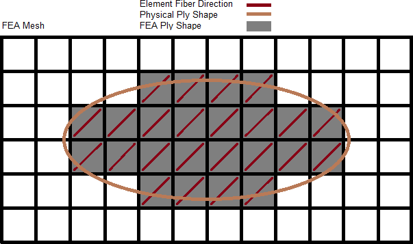
The shape (area) of an FEA ply is defined by selecting elements which most closely represent the complex shape of a physical ply. In the example below, an elliptical physical ply shape is defined by the brown line. The corresponding FEA ply shape is defined by the gray shaded elements of the associated FEA mesh. Typically, if an element's centroid exists within the bounds of the physical ply shape, that element is considered part of the FEA ply shape.
Instead of defining plies through an element selection, they can be defined by selecting lines which have to build a closed area. If CPD data is read from Catia files, plies come in defined on lines.
Once a mesh is available, plies defined by lines can be converted into plies defined by elements by selecting the Realize function from the Model browser's context menu. Three realization/conversion methods are available:
| • | Project normal to target mesh: If the element centroid projected along its normal lies within the geometrical ply definition, it is associated with this ply. |
| • | Normal by ply contour: Projection along a normal on a surface derived from the lines of a ply contour. |
| • | Specified direction: You can define a projection direction. |
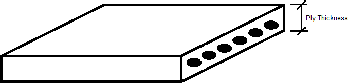
The ply thickness is typically defined as the final cured thickness of a single ply of material as shown below. In addition, the ply can be made of any material: isotropic, orthotropic, anisotropic, or any other material law.
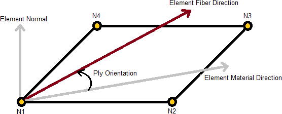
The fiber orientation of a ply defines the direction fibers lay within that ply. The ply fiber orientation is typically an integer value between -90 and 90. The fiber orientation of a ply is always defined relative to each elements material direction using right hand rule around the elements normal, or thru-thickness direction, to define positive angles. Even though a ply's fiber orientation is a constant integer, element material directions can vary from element to element, and this allows varying fiber directions within a ply to be modeled. Element material directions are defined differently from solver to solver, and can be defined in the HyperMesh Composites panel.
Once all the plies which make up a composite structure are defined, just as in the actual hand-layup manufacturing process, plies are stacked in a specific given order within the laminate entity to define a laminate of the structure. It is possible to stack plies, whether they are defined based on geometry or elements.
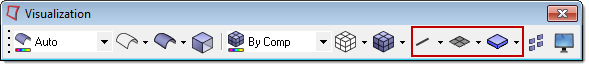
Plies have a display state, on or off, which controls the display of a ply in the graphics area. The display state of a ply can be controlled using the icon next to the ply entity in the Model browser. In addition, in order for plies to be displayed on the screen, the composite layers visualization mode must be turned on. The composite layers visualization mode displays the layers within every element which have proper laminate definitions and composite properties assigned. Plies can be displayed in a traditional shell representation or in a 3D representation by turning on the appropriate element representation visualization mode. Both the element representation and composite layers visualization modes can be set on the Visualization toolbar.
Plies also have an active and export state. These states of ply entities can be controlled using the Entity State browser:
| • | The active state of a ply controls the listing of the ply in the Model browser and any of its views. If a ply entity is active, then it is listed in the Model browser and any of its views. If a ply entity is inactive, then it is not listed in the Model browser or any of its views. |
| • | The export state of a ply entity controls whether or not that ply is exported when the custom export option is utilized. The all export option is not affected by the export state of a ply. |
The data names associated with plies can be found in the data names section of the HyperMesh Reference Guide.
The OptiStruct PLY card is represented in HyperMesh as a ply entity. Ply entities are created and edited using the ply create and edit dialogs from the Model browser. Plies can be created from selection of individual elements or from predefined element sets which define the ply shape.
|
The Abaqus solver has no direct match for a ply. Thus, the ply entity does not have a card image in the Abaqus interface. Ply entity names will end up in the ply name of the composite properties SHELL SECTION and SHELL GENERAL SECTION, if used in a laminate entity and realized into a zone based model (see laminate entity for details).
|
The Nastran solver has no direct match for a ply. Thus, the ply entity does not have a card image in the Nastran interface. Ply entity IDs will end up as global ply ID in the PPOMG property card, if used in a laminate entity and realized into a zone based model (see laminate entity for details). |
