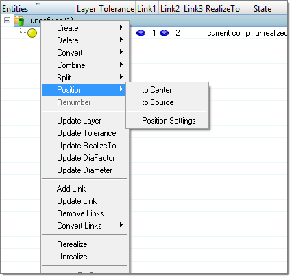
Use the Position option to place a connector in-between the center of the two farthest defined links or its source position.
To use this option, highlight the connector(s) you want to position, then right-click and select Position > Style option from the context menu. The source position is the position of the connector before it has been positioned in the center.
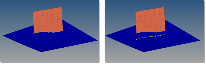
In the case of line connectors, each individual connector point is centered.
| Note: | The source position of a connector is saved on the connector during the centering, therefore it is possible to go back to the origin position. There are certain actions, which reset the source position to the current one. This happens, for example, when splitting or translating a connector. Also, the source position is only available in the current session; it will not be saved in either the Engineering Solutions file or in the .xml file. |
Bolt and Area connectors are not supported for the positioning.
If a connector is defined with the link conservation option use extra links, it might be, that positioning to the center provides unexpected results because all of the links with valid projections are considered, even if they are not needed for the final realization.
|
In the position settings further control parameter can be defined.
Option
|
Description
|
Consider only
|
These settings help to filter down the connector selection to those whom should be considered for the intended positioning. Exclusively connectors with the checked attributes are considered
| • | Spots. Consider spot connectors. |
| • | Seam. Consider seam connectors. |
| • | Unrealized. Consider unrealized connectors. |
| • | Realized. Consider realized connectors. |
| • | Failed. Consider failed connectors. |
| • | =2t. Consider connectors with a number of layers equal to 2. |
| • | >2t. Consider connectors with a number of layers greater than 2. |
|
Upon Positioning
|
Functionality to use for FE representation during or after the positioning of connectors that have already been realized.
| • | Unrealize. Unrealize all of the connectors being considered for positioning. Registered FE elements will be deleted. |
| • | Rerealize. Realize all of the connectors being considered for positioning, starting from their new position. |
| • | Accept wo Reconfirmation. Place all of the connectors being considered for positioning in their new location without doing anything to the realized FE. |
This option is only recommended for simple realization types with smaller extensiveness, since these use a similar projection logic than the center positioning.
There is always the risk that a formerly successful realized connector fails after the center positioning. The risk increases with the complexity of the realization type.
|


