|
»Click here to display Table of Contents«
|

Add Link |

|

|

|

|
|
Add Link |
|
|
|

|
|
»Click here to display Table of Contents«
|
Add Link |
|
|
|
|
|
Add Link |
|
|
|
|
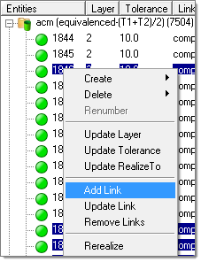
Use the Add Link option to add links (component, assembly, surface. element, tag, node) at a time to one or more connectors. To access this option, right-click on the connector(s) that you wish to add links to, and then select Add Link from the context menu. Once enabled, the Add Link window opens at the bottom of the Connector browser.
All of the connectors highlighted in the connector list at the time the Add Link tool is enabled, will be affected. If you wish to cancel the add link function, click Reject (located in the upper right-hand corner of the Add Link tool).
The Add Link window is laid out in a table format, with each Add Link option displayed in the Name column, and the controls and values associated with each option displayed in the Value column to the right.
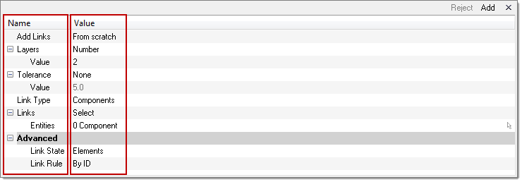
The following options are displayed in the Add Link window:
Option |
Description |
||||||||||||||||||||
|---|---|---|---|---|---|---|---|---|---|---|---|---|---|---|---|---|---|---|---|---|---|
Add Links |
Determine how you will be adding links. Click the Value column to select one of the two Add Link options from the pull-down menu:
|
||||||||||||||||||||
Layers |
Select the number of thicknesses (layers) for the connectors. Click the Value column to select one of the following Layers options from the pull-down menu:
|
||||||||||||||||||||
Tolerance |
Select the tolerance to be used for link detection. If the link candidates are close enough to the connector (within the tolerance), then they could become links as long as other conditions are not fulfilled. Click the Value column to select one of the following Tolerance options from the pull-down menu:
|
||||||||||||||||||||
Link Type |
Select the type of entity that can be added to the selected connector(s) as a link reference. Click the Value column to select one of the following options from the pull-down menu: Components, Properties, Assemblies, Surfaces, Tags, Elements, Nodes, and Parts. |
||||||||||||||||||||
Links |
Select which entities in the model to which the connector will link to. The selection made from the Link Type option above will influence what is displayed in this option. Click the Value column to select one of the following options from the pull-down menu:
|
||||||||||||||||||||
Link State |
Determines whether the weld created during connector realization connects to geometry or mesh on the link. This option is significant for link detection. Only the entities of the right state, meaning elements or surfaces, will be taken into account. If the link state is set to geometry, then close elements will not be considered for link detection. Click the Value column to select one of the following Link State options from the pull-down menu:
|
||||||||||||||||||||
Link Rule |
Defines how a connector treats an entity added as a link. Click the Value column to select one of the following Link Rule options from the pull-down menu:
|