This process template sets up subcases with unit inputs. In practice, this is common to generate vibration and noise sensitivity results.
In this task, pick either the Direct Frequency Response solution method, or the Modal Frequency Response solution method. For large problems involving more than a few frequencies, the modal solution is typically the most efficient solution.
|
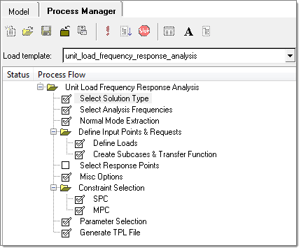
In this task, enter the frequencies for which the response solution is needed. Choose one of three ways to define the frequency set:
| 1. | Min., Max, and a linear step |
| 2. | Min., Max, and a number of increments with logarithmic spacing |
| 3. | An arbitrary list of frequencies |
For options 1 and 2, select the Frequency range radio button and an Increment type (Linear or Logarithmic), and fill in the required fields. For option three, simply type in a list of arbitrary frequencies, then click Update. A frequency set entry is created in the list box to the left. You can add additional frequency sets, or delete one from the list using the Add row and Delete row icons to the right of the list. Once the frequency set(s) has been defined, click Apply to proceed to the next task.
|
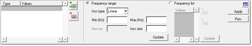
This task is essentially the same the previous step. The default frequencies filled in are based on the max. frequency entered in the previous task. These are merely the suggested values based on general use cases, and should be modified based on the specific requirements of the case under study.
|
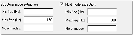
In this task, define what type of load is applied where. Supported load types include:
| • | Enforced motion (displacement, velocity, or acceleration) |
The first four types are only applicable for structural nodes, and the last one for fluid nodes.
Once a type is selected, click the Nodes entity selector to pick nodes, a node set, or tags in the graphics window, then click Add. This will populate the table on the left hand side with additional degree of freedom (DOF) checkboxes available. You can make a single or multiple row selection within the table, and then right click to access the DOF row selection options. Alternatively, make a single or multiple row selection within the table, and then right click to access the column selection options. All selected DOFs will be checked to indicate locations and directions where unit input are to be applied. Upon clicking Apply, one loadcase will be created for each DOF indicated.
|
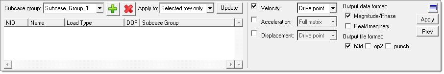
This task lets you select to output transfer function between input points. Of particular interest are driving point (response taken at the same point as input) transfer functions, which are commonly used as a measure for local dynamic stiffness, or full matrix (all possible pairs of input point combinations) output, which is sometimes used as input for FRF based substructuring analysis.
It is also possible to create new subcase groups of input to be used in individual subcases. New subcase groups can be added by clicking the Add Group icon  . You can make a single or multiple row selections within the table, and then select the newly created Subcase group and click Update. All input dofs belonging to one subcase group will be used as simultaneous excitations in one subcase. . You can make a single or multiple row selections within the table, and then select the newly created Subcase group and click Update. All input dofs belonging to one subcase group will be used as simultaneous excitations in one subcase.
|
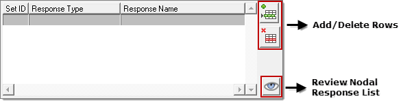
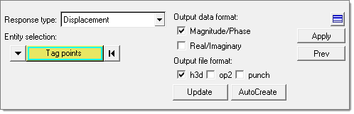
This task lets you pick responses for output. First select a response type, such as Displacement, then pick nodes, a node set, or tags to be included in a particular response set. You can add or delete multiple response sets from the list using the Add row and Delete row icons to the right of the list. You can also specify the complex frequency response data format (real/imaginary or magnitude/phase) and the output file format (h3d, punch, or op2). Once all the required responses have been defined, click Apply to proceed to the next task.
|
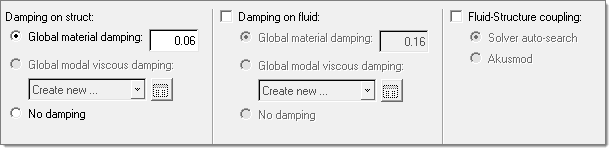
Select from the damping options that are available, including the global modal viscous damping on the structure side, and global material and viscous damping on the fluid side.
|
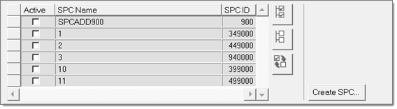
This task lets you define the boundary condition of the frequency response analysis. You can select existing SPCs by checking the corresponding box under the Active column, or click Create SPC to go to the Constraints panel and define a new SPC. Once the boundary condition has been fully defined, click Apply to proceed to the next task.
|
This task lets you select MPC equations to turn on for the frequency response analysis. You can only select existing MPCs by checking the corresponding box under the Active column. Once the MPC equations have been selected, click Apply to proceed to the next task.
|
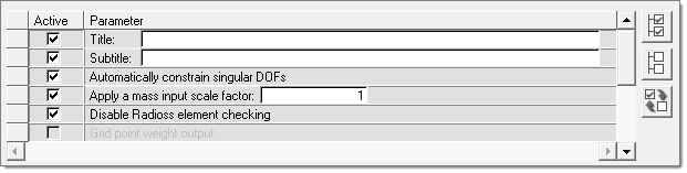
This task lets you select typical solution parameters, such as title, singular point constraints, and so on. Check all boxes under the Active column to activate the desired solution option. Once the parameters have been selected, click Apply and a Process Manager message box pops up informing you that the process has come to an end. Click Yes to close the template, or No to review or edit the process steps.
|
This task allows you to generate and save the parameters defined in a standard template file at your selected location.
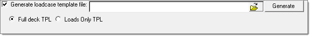
There are two options to define the standard template file:
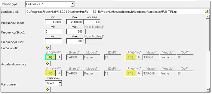
| • | Full deck TPL: This file has all of the parameters for the complete unit load FRF process manager. In the Analysis Manager, the generated template file can be selected as loadcase for the Solution type Full deck TPL and solver decks can be exported for the unit FRF. |
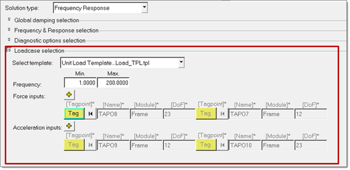
| • | Loads Only TPL: This file only has the parameters for the loadcase portion of the unit load FRF process manager. In the Analysis Manager, the generated template file can be selected as the loadcase for the Solution type Frequency Response and solver decks can be exported for general FRF. |
|


