|
»Click here to display Table of Contents«
|

Wind Tunnel Meshing |

|

|

|

|
|
Wind Tunnel Meshing |
|
|
|

|
|
»Click here to display Table of Contents«
|
Wind Tunnel Meshing |
|
|
|
|
|
Wind Tunnel Meshing |
|
|
|
|
The Wind Tunnel Mesh button on the Utility menu opens the Wind Tunnel Meshing function. A hexahedral mesh is created inside the volume defined by points one through eight as shown below.
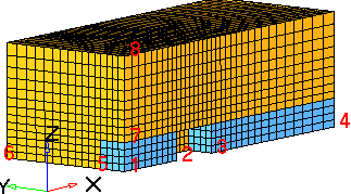
Hexas are placed in a new component named fluid_hex.
Pyramids are created on all the quad faces defining the empty pocket shown (2-3). Pyramids are included in component fluid_hex. Component edges_xy and edges_xz are created to generate the 2D meshes that are later used to define the bounding box in the CFD Tetramesh panel.
Boundary condition zones are generated in components: inlet, outlet, ground, wallroof, symp and wallside.
To use the interactive image below, roll your mouse over the image for a description of the various options. |