HyperMesh and BatchMesher

Connector Panels

Connector Panels

Previous topic Next topic Expand/collapse all hidden text  

Connector Panels

Previous topic Next topic JavaScript is required for expanding text JavaScript is required for the print function  

This section concentrates on the structure in the Spot, Bolt, Seam and Area panels. These can be found in the connectors module and are the main panels used for connector creation, realization and editing. The structures of these panels are very comparable.

They are all subdivided in at least three subpanels:

spot/bolt/seam/area: the connector of appropriate type is both created and realized in one shot
create: the connector of appropriate type is created only
realize: an existing connector of appropriate type is realized only


Whereas the edit or the partition subpanels are different or belong exclusively to a certain connector type, these three subpanels look and behave very similarly.

connector_panel_organization

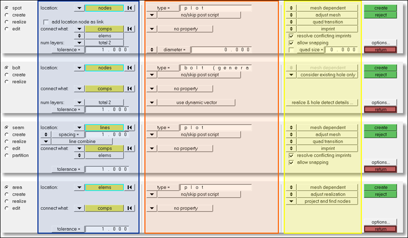
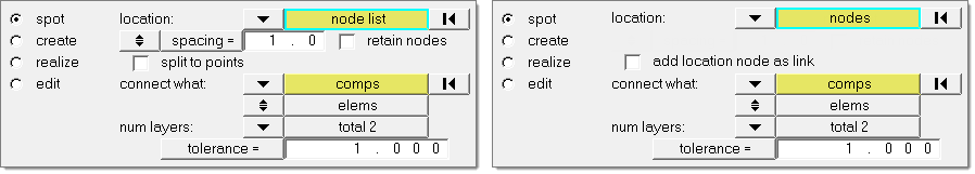
The subpanels are organized into three columns, shown here with colored boxes.

hmtoggle_plus1greyFirst Column (blue)

This column contains everything related to connector creation and link detection. In this column, you will define the following:

location
link candidates (link entity type, link state)
number of layers (only for spots and bolts), and
tolerance


Dependent on the connector type (spot, bolt, seam, area) and the selected locations, additional options are provided. The most important are:

spacing/density

defines how the test points should be distributed along a connector line. At each test point a separate realization is performed. This is also available for spot or bolt connectors.

split to points

available for any kind of elongated connector location like line, linelist, or nodelist. The test points are distributed along this line, but single connectors instead of a line connector are created.

add location node as link

available only for spots defined at node locations. The selected node is stored on the connector as link entity.

connector_panel_organization_column1

These first (blue highlight) columns look exactly the same on the different create subpanels.


hmtoggle_plus1greySecond Column (orange)

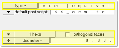
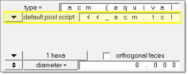
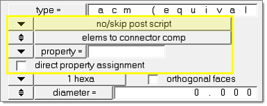
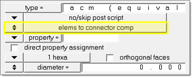
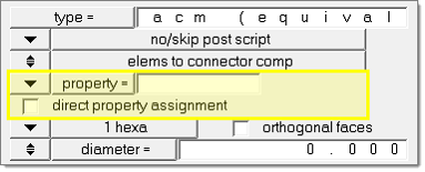
This column contains everything related to realization type, post script, and property assignment.

In the first line of this column the realization type is selected.
In the last two lines, different options are provided dependent upon the realization type. See the different connector realization types for more details.

connector_panel_organization_column2a

Many custom realization types include a certain post script. If such a realization type is chosen, the default post script is set to the appropriate post script. These types of post scripts typically manage the organization and property assignment of the FE representation.

In the second line the post script treatment is defined. This can be done for any realization type, even for those with a post script defined in the FE configuration file. The options are:

default post script

Default for any realization type having a post script defined in its FE configuration, though this option can be changed (sometimes you may wish to skip the predefined post scripts or to use your own).

connector_panel_organization_column2b

no/skip post script

Default for all realization types without any post script defined. No post script is used. When this option is chosen, several additional entry controls appear.

connector_panel_organization_column2c

user post script

You must specify your own tcl file to be used. Such a file can perform a special treatment on the FE representation.

In the third line the element destination can be defined. This line only appears in the create subpanels when no/skip post script is selected in the second line.

connector_panel_organization_column2d

elems to current comp

The newly created elements are organized into the current component.

elems to connector comp

The newly created elements are organized appropriate to the connector component.

In the fourth and fifth lines the property treatment is defined. This line only appears when no/skip post script is selected in the second line.

connector_panel_organization_column2e

property =

Select a property to assign to all newly created elements.

no property

No property is created.

direct property assignment

Select this check box to directly assign the property. When unselected, the property is assigned to the destination components. This option is only available when property= is selected and the user profile is Nastran, OptiStruct, RADIOSS, or Abaqus.

These second (orange) columns look exactly the same on all the different realize subpanels.


hmtoggle_plus1greyThird Column (yellow)

This column contains options related to the final connection to the link entities. This column is the same for all of the different realize subpanels.

The realization type describes how the FE representation will look. HyperMesh offers different routines to determine how the realizations should occur. These different routines describe in more detail exactly how the connection between the FE representation and the link elements should be achieved. The routines differ depending on the connector type; similar methods are offered for spots, seams, and area connectors, but bolt connectors require completely different methods.

Note:Certain realization types need specific realization methods, or offer only a subset of the available methods.

The realization methods can be chosen in every subpanel where a connector realization can be performed. These subpanels are always the 1st and 3rd subpanel in the Spot, Bolt, Seam, and Area panels. In each case, the first subpanel creates and subsequently realizes the connector, while the third subpanel realizes preexisting connectors. All of these subpanels are divided into three sections; the right section is the one with the different realization methods.


See Also:

connectors module