In this tutorial, you will learn how to:
| • | Load the Abaqus user profile and model |
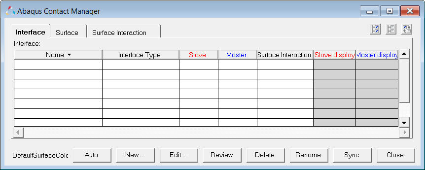
| • | Start the Abaqus Contact Manager |
| • | Define surfaces for solid elements |
| • | Define surfaces for shell elements |
| • | Define surface interaction property |
Model Files
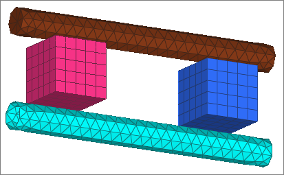
This exercise uses the contactManager_3D_tutorial.hm file, which can be found in <hm.zip>/interfaces/abaqus/. Copy the file(s) from this directory to your working directory.
Exercise
Step 1: Load the Abaqus user profile and model
A set of standard user profiles is included in the HyperMesh installation. They include: OptiStruct, Abaqus, Actran, ANSYS, LS-DYNA, MADYMO, Nastran, PAM-CRASH, PERMAS, and RADIOSS. While the user profiles change the appearance of some panels, they do not affect the internal behavior of each function.
| 1. | Start HyperMesh Desktop. |
| 2. | In the User Profile dialog, set the user profile to Abaqus, Standard 3D. |
| 3. | Open a model file by clicking File > Open > Model from the menu bar, or clicking  on the Standard toolbar. on the Standard toolbar. |
| 4. | In the Open Model dialog, open the contactManager_3D_tutorial.hm file. The model appears in the graphics area. |
Step 2: Start the Contact Manager
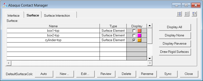
| 1. | From the menu bar, click Tools > Contact Manager. The Abaqus Contact Manager opens. |
Steps 3 - 5: Defining Surfaces for Solid Elements
In HyperMesh, you can define the *SURFACE, TYPE=ELEMENT card by using individual element IDs or sets with corresponding face identifiers. In this exercise, you will create surfaces by defining individual element IDs and corresponding faces.
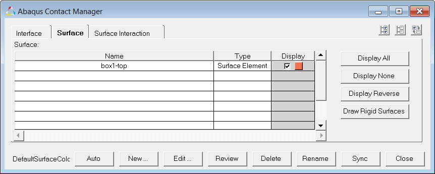
Step 3: Create the "box1-top" surface
| 1. | In the Abaqus Contact Manager, click the Surface tab. |
| 2. | Click New. The Create New Surface dialog opens. |
| 3. | In the Name field, enter box1-top. |
| 4. | Set Type to Element based. |
| 5. | Click the box next to Color and select a color. |
| 6. | Click Create. The Element Based Surface dialog opens, from which you can define elements and corresponding faces for the surface. |
| 7. | In the Model browser, Component folder, right-click on BOX_1 and select Isolate from the context menu. |
| 8. | On the Standard Views toolbar, click  (XY Top Plane View). (XY Top Plane View). |
| 9. | In the Element Based Surface dialog, click the Define tab. |
| 10. | Set Define surface for to 3D solid, gasket. |
| 12. | In the panel area, click elems >> by collector. |
| 13. | Select the component, BOX_1. |
| 14. | Click select. The elements in the BOX_1 component highlight. |
| 15. | Click proceed to return to the Element Based Surface dialog. |
| 16. | Set Select faces by to Solid skin. |
| 17. | Select a color from the Solid skin color button. |
| 18. | Click Faces. HyperMesh creates a temporary skin of the selected elements. |
| 19. | Select an element from the top of the solid skin. |
| 20. | In the panel area, click elems >> by face. All faces at the top of the solid skin highlight. |
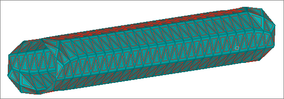
| 21. | Rotate the model to verify all desired faces are selected. |
| 22. | Optional. Deselect any element by right-clicking or add more if you like. |
| 23. | When you are satisfied with the element faces selected, click proceed to return to the Element Based Surface dialog. |
| 24. | Click Add to add these faces to the current surface. HyperMesh creates special face elements (rectangles with dot in the middle) for display. |
| 25. | Optional. Reject the recently added faces by clicking Reject. You can also delete faces from the Delete page. |
| 26. | When satisfied with the surface definition, click Close to return to the Abaqus Contact Manager. |
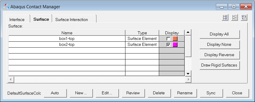
Step 4: Create the "box2-top" surface
| 1. | In the Abaqus Contact Manager, click the Surface tab. |
| 2. | Click Display None to turn off the display of all surfaces. |
| 3. | Click New. The Create New Surface dialog opens. |
| 4. | In the Name field, enter box2-top. |
| 5. | Set Type to Element based. |
| 6. | Click the box next to Color and select a color. |
| 7. | Click Create. The Element Based Surface dialog opens, from which you can define elements and corresponding faces for the surface. |
| 8. | In the Model browser, Component folder, right-click on BOX_2 and select Isolate from the context menu. |
| 9. | On the Standard Views toolbar, click (XY Top Plane View). |
| 10. | In the Element Based Surface dialog, click the Define tab. |
| 11. | Set Define surface for to 3D solid, gasket. |
| 13. | In the panel area, click elems >> by collector. |
| 14. | Select the component, BOX_2. |
| 15. | Click select. The elements in the BOX_2 component highlight. |
| 16. | Click proceed to return to the Element Based Surface dialog. |
| 17. | Set Select faces by to Nodes on face. |
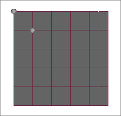
| 19. | Select two corner nodes (or three nodes) from the top of the selected solids as shown below. |
| 20. | In the panel area, click proceed to return to the Element Based Surface dialog. |
| 21. | In the Break Angle field, enter 30.00. |
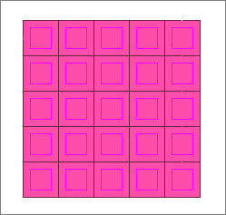
| 22. | Click Add to find all of the faces of the selected solids that fall within the break angle of the face defined by nodes. HyperMesh adds these faces to the current surface and creates special face elements (rectangles with dot at the middle) for display. |
| 23. | Optional. Reject the recently added faces by clicking Reject. You can also delete faces from the Delete page. |
| 24. | When satisfied with the surface definition, click Close to return to the Abaqus Contact Manager. |
Step 5: Create the "cylinder-top" surface
| 1. | In the Abaqus Contact Manager, click the Surface tab. |
| 2. | Click Display None to undisplay all surfaces. |
| 3. | Click New. The Create New Surface dialog opens. |
| 4. | In the Name field, enter cylinder-top. |
| 5. | Set Type to Element based. |
| 6. | Click the Color button and select a color. |
| 7. | Click Create. The Element Based Surface dialog opens, from which you can define elements and corresponding faces for the surface. |
| 8. | In the Model browser, Component folder, right-click on TOP_CYLINDER and select Isolate from the context menu. |
| 9. | In the Element Based Surface dialog, click the Define tab. |
| 10. | Set Define surface for to 3D solid, gasket. |
| 12. | In the panel area, click elems >> by collector. |
| 13. | Select the component, TOP_CYLINDER. |
| 14. | Click select. The elements in the TOP_CYLINDER component highlight. |
| 15. | Click proceed to return to the Element Based Surface dialog. |
| 16. | Set Select faces by to Solid skin. |
| 17. | Select a color from the Solid skin color button. |
| 18. | Click Faces. HyperMesh creates temporary skin of the selected elements. |
| 19. | Select an element from the solid skin. |
| 20. | In the panel area, click elems >> by face. The faces all around the solid skin highlight. |
| 21. | Rotate the model to verify all desired faces are selected. |
| 22. | Optional. Deselect any element by right-clicking, or add more if you like. |
| 23. | When you are satisfied with the element faces selected, click proceed to return to the Element Based Surface dialog. |
| 24. | Click Add to add these faces to the current surface. HyperMesh creates special face elements (rectangles with dot at the middle) for display. |
| 25. | Optional. Reject the recently added faces by clicking Reject. You can also delete faces from the Delete page. |
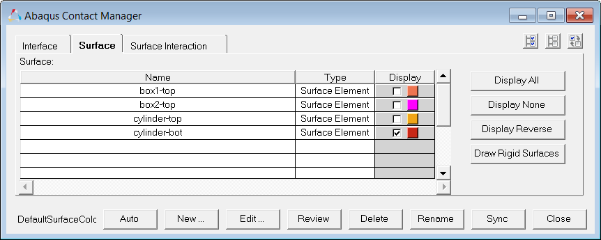
| 26. | When satisfied with the surface definition, click Close to return to the Abaqus Contact Manager. |
Step 6: Define surfaces for shell elements
In HyperMesh, you can define the *SURFACE, TYPE=ELEMENT card by using individual shell element IDs or sets with corresponding SPOS/SNEG face identifiers. In this exercise, you will create surfaces by defining individual element IDs and corresponding normals to define the SPOS/SNEG faces.
Complete the steps below to create the "cylinder-bot" surface:
| 1. | In the Abaqus Contact Manager, click the Surface tab. |
| 2. | Click Display None to undisplay all surfaces. |
| 3. | Click New. The Create New Surface dialog opens. |
| 4. | In the Name field, enter cylinder-bot. |
| 5. | Set Type to Element based. |
| 6. | Click the Color button and select a color. |
| 7. | Click Create. The Element Based Surface dialog opens, from which you can define elements and corresponding faces for the surface. |
| 9. | Set Define surface for to 3D shell, membrane, rigid. |
| 10. | In the Model browser, Component folder, right-click on BOT_CYLINDER and select Isolate from the context menu. |
| 11. | In the Element Based Surface dialog, click Elements. |
| 12. | In the panel area, click elems >> by collector. |
| 13. | Select the component, BOT_CYLINDER. |
| 14. | Click select. The elements in the BOT_CYLINDER component highlight. |
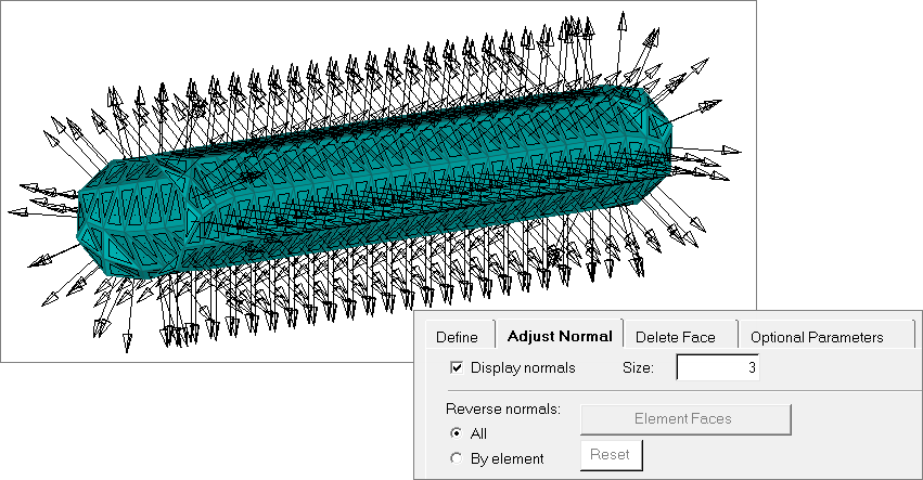
| 16. | The normals of the selected elements will be displayed at this point. If the normals are too big, click  (YZ Front Plane View) on the Standard Views toolbar. (YZ Front Plane View) on the Standard Views toolbar. |
Notice that all normals are pointing inwards.
| 17. | Check the Reverse option. |
| 18. | Click Add to add these faces to the current surface. HyperMesh creates special face elements (rectangles with dot at the middle) for display. |
| 19. | Optional. Reject the recently added faces by clicking Reject. You can also delete faces from the Delete page. |
| 20. | Click the Adjust Normal tab. |
| 21. | Click Display normals. The normals of all the faces in the current surface display. |
Notice that all normals are pointing outwards.
| 22. | When satisfied with the surface definition, click Close to return to the Abaqus Contact Manager. |
Steps 7 - 8: Define Surfaces by Set
In HyperMesh, you can define the *SURFACE, TYPE=ELEMENT card by using individual element IDs or sets with corresponding face identifiers. In this exercise, you will create surfaces by defining a set and corresponding face identifiers. HyperMesh allows only one set in a surface. It also does not support a combination of sets and individual elements in the same *SURFACE data line.
Step 7: Create the box1-bot surface
| 1. | In the Abaqus Contact Manager, click the Surface tab. |
| 2. | Click Display None to undisplay all surfaces. |
| 3. | Click New. The Create New Surface dialog opens. |
| 4. | In the Name field, enter box1-bot. |
| 5. | Set Type to Element based. |
| 6. | Click the Color button and select a color. |
| 7. | Click Create. The Element Based Surface dialog opens, from which you can define elements and corresponding faces for the surface. |
| 9. | Set Define surface for to Element set. |
| 10. | In the Model browser, Component folder, right-click on BOX_1 and select Isolate from the context menu. |
| 11. | On the Standard Views toolbar, click  (YX Bottom Plane View). (YX Bottom Plane View). |
| 12. | In the Element Based Surface dialog, set Element set to box1-bot. |
| 13. | Click Review Set to highlight all of the elements in the selected set. |
| 14. | Right-click on Review Set to reset the highlighting. |
| 15. | Click Show Faces. HyperMesh creates a temporary skin of the selected element set. |
| 16. | Select an element from the bottom of the solid skin. |
| 17. | In the panel area, click elems >> by face. All of the faces on the bottom of the solid skin highlight. |
| 18. | Optional. Deselect any element by right-clicking, or add more if you like. |
| 19. | When you are satisfied with the element faces selected, click proceed to return to the Element Based Surface dialog. |
At this point, the face identifier tags (color coded) of the selected faces are displayed. In performance graphics, the solid mesh sometimes blocks these tags. You might have to rotate the model a little to make these tags visible or switch to Standard graphics.
| 20. | Click the right arrow key to move the box1-bot set into the table. |
| 21. | In the table, click on the Face pull down menu and select S3. |
| Note: | Because all of the face identifier tags for the bottom side of the box1-bot set are S3, you can use the S3 identifier for this set. |
| 22. | Select the Display checkbox, and then click Update. HyperMesh adds the selected set and face identifier to the current surface. In addition, it creates a special display for the surface. |
By default, HyperMesh does not create a display for surfaces defined with sets. However, if you select the Display checkbox before clicking Update, it will create a special display using contactsurface elements. The special display does not have any link to the set in the HyperMesh database. Therefore, if you edit the set later on, the display will not reflect them automatically. In this case, you need to come to this page, select the Display checkbox and click Update again.
| 23. | Click Close to return to the Abaqus Contact Manager. |
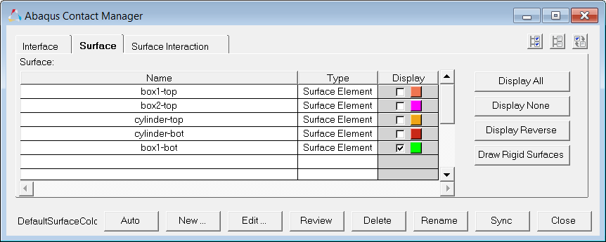
Step 8: Create the box2-bot surface
| 1. | In the Abaqus Contact Manager, click the Surface tab. |
| 2. | Click Display None to undisplay all surfaces. |
| 3. | Click New. The Create New Surface dialog opens. |
| 4. | In the Name field, enter box2-bot. |
| 5. | Set Type to Element based. |
| 6. | Click the Color button and select a color. |
| 7. | Click Create. The Element Based Surface dialog opens, from which you can define elements and corresponding faces for the surface. |
| 9. | Set Define surface for to Element set. |
| 10. | In the Model browser, Component folder, right-click on BOX_2 and select Isolate from the context menu. |
| 11. | On the Standard Views toolbar, click (YX Bottom Plane View). |
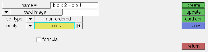
| 12. | In the Element Based Surface dialog, click Create/Edit Sets. |
| 13. | In the panel area, enter box2-bot in the name field. |
| 14. | Click elems >> by collector. |
| 15. | Select the component, BOX_2. |
| 18. | When you are done creating/editing the set, click return. |
| 19. | Set Element set to box2-bot. |
| 20. | Click Review Set to highlight all of the elements in the selected set. |
| 21. | Right-click on Review Set to reset the highlighting. |
| 22. | Click Show Faces. HyperMesh creates a temporary skin of the selected element set. |
| 23. | Select an element from the bottom of the solid skin. |
| 24. | In the panel area, click elems >> by face. All of the faces on the bottom of the solid skin highlight. |
| 25. | Optional. Deselect any element by right-clicking, or add more if you like. |
| 26. | When you are satisfied with the element faces selected, click proceed to return to the Element Based Surface dialog. |
At this point, the face identifier tags (color coded) of the selected faces display. In performance graphics, the solid mesh sometimes blocks these tags. You might have to rotate the model a little to make these tags visible or switch to standard graphics.
| 27. | Click the right arrow to move the box2-bot set into the table. |
| 28. | In the table, click on the Face pull down menu and select S3. |
| Note: | Because all of the face identifiers tags for the bottom side of the box2-bot set are S3, you can use the S3 identifier for this set. |
| 29. | Clear the Display checkbox if it is selected, then click Update to add the selected set and face identifier to the current surface. |
| Note: | By default, HyperMesh does not create any display for surfaces defined with sets. |
| 30. | Click Close to return to the Abaqus Contact Manager. |
| Note: | Notice in the Surface table that the Display option for the box2-bot surface is disabled. |
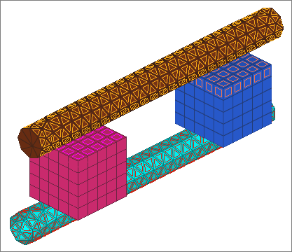
At this point, you have created all of the required surfaces.
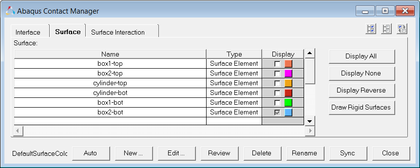
| 31. | Click Display All to display all surfaces. |
| 32. | In the Model browser, right-click on the Components folder and select Show from the context menu. All of the components display. |
| 33. | On the Standard Views toolbar, click  (Isometric). (Isometric). |
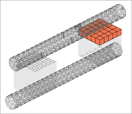
| 34. | Review a surface by selecting it from the table and clicking Review. Selected surfaces will be highlighted in red, while the rest of the model displays in gray. If the surface is defined with sets (display option disabled), the underlying elements are highlighted. Right-click on Review to clear the highlighting. |
Step 9: Define the surface interaction property
In this exercise, you will define the *SURFACE INTERACTION card with a corresponding *FRICTION card.
Complete the steps below to create the "friction1" surface interaction.
| 1. | In the Abaqus Contact Manager, click the Surface Interaction tab. |
| 2. | Click New. The Create New Surface Interaction dialog opens. |
| 3. | In the Name field, enter friction1. |
| 4. | Click Create. The Surface Interaction dialog opens. |
| 6. | Under Select mechanical interaction properties, select Friction. The Friction tab becomes active. |
| 7. | Click the Friction tab. |
| 8. | Set Friction type to Default. |
| 9. | In the second pane, select Direct. |
| Note: | Selecting this option means that the exponential decay and Anisotropic parameters will not be written to the input file. |
| 10. | In the No of data lines field, enter 1. A single row appears in the Direct table. |
| 11. | In the Friction Coeff column, click the first cell and enter 0.05. |
For Direct and Anisotropic tables:
| • | Change the number of columns in the table by specifying a value in the No of Dependencies field; change the number of rows in the table by specifying a value in the No of data lines field. |
| • | Enter values in the table by clicking a cell to make it active and then typing in values. The table works like a regular spreadsheet. |
| • | Read comma-delimited data from a text file by clicking Read From a File. In the file browser, select a file and click Open to export the comma-delimited data. The row number will be set to the number of data lines found in the file. |
| • | Access copy, cut, and paste options by right-click in the table. Comma-separated data can be copied/cut into or pasted from clipboard with these options. Relevant hot keys (for example, Ctrl-C, Ctrl-X and Ctrl-V in Windows) will also work. |
| • | Activate cells by left-clicking in a cell. Clicking into an already active cell moves the insertion cursor to the character nearest the mouse. |
| • | Highlight cells by left-clicking while moving the mouse over a cell. |
| • | Move the active cell using the left, right, up, and down arrows. |
| • | Extend the selection in a specific direction using SHIFT-<arrow>. |
| • | Move the insertion cursor within a cell using CTRL-left arrow and CTRL –right arrow. |
| • | Selects all cells using CTRL -slash. |
| • | Delete the character before the insertion cursor in the active cell using BACKSPACE. If multiple cells are selected, BACKSPACE deletes all selected cells. |
| • | Remove the character after the insertion cursor in the active cell using DELETE. If multiple cells are selected, DELETE removes all selected cells. |
| • | Move the insertion cursor to the beginning of the active cell using CTRL-A. Move the insertion cursor to the end of the active cell using CTRL-E. |
| • | Decrease and increase the width of the column with the active cell in it using CTRL-minus (-) and CTRL-equal (=). |
| • | Interactively resize a row or column by left-clicking or right-clicking on a border while moving the mouse. |
| 11. | Click OK to return to the Abaqus Contact Manager. |
Steps 10-13: Define the Contact Pairs
In this exercise, you will define the *CONTACT PAIR card with corresponding surfaces and surface interaction.
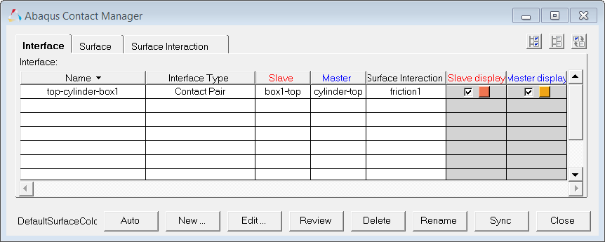
Step 10: Create the top-cylinder-box1 contact pair
| 1. | In the Abaqus Contact Manager, click the Interface tab. |
| 2. | Click New. The Create New Interface dialog opens. |
| 3. | In the Name field, enter top-cylinder-box1. |
| 4. | Set Type to Contact pair. |
| 5. | Click Create. The Contact Pair dialog opens. |
| 7. | Set Surface to box1-top. |
| 8. | Click Slave>> to identify box1-top as the slave surface and move it into the table. |
| 9. | Click Review. The selected surface highlights red. If the surface is defined with sets (display option disabled), the underlying elements highlight. Right-click on Review to clear the highlighting. |
Clicking New opens the Create New Surface dialog, from which you can create a new surface. When you are done creating and defining the surface, the Contact Pair dialog returns with the new surface selected as the slave surface.
| 10. | Repeat steps 10.7 and 10.8, selecting cylinder-top and clicking Master>> to identify it as the master surface. |
| Note: | To more clearly see the surfaces available for selection, click  . This opens an enhanced browser where you can easily search for the appropriate item. You can also click Filter to filter the items displayed. . This opens an enhanced browser where you can easily search for the appropriate item. You can also click Filter to filter the items displayed. |
| 11. | Set Interaction to friction1. |
| Note: | To more clearly see the interactions available for selection, click . This opens an enhanced browser where you can easily search for the appropriate item. You can also click Filter to filter the items displayed. |
| 12. | Click the Parameter tab. |
| 13. | Select the Small sliding checkbox. |
| 14. | Click OK to return to the Abaqus Contact Manager. |
Step 11: Create the top-cylinder-box2 contact pair
Follow step 10.1 through 10.14 above to define the top-cylinder-box2 contact pair with box2-top as slave surface, cylinder-top as master and friction1 as the surface interaction.
Step 12: Create the bot-cylinder-box1 contact pair
Follow step 10.1 through 10.14 above to define the bot-cylinder-box1 contact pair with box1-bot as slave surface, cylinder-bot as master and friction1 as the surface interaction.
Step 13: Create the bot-cylinder-box2 contact pair
Follow steps 10.1 through 10.14 above to define the bot-cylinder-box2 contact pair with box2-bot as slave surface, cylinder-bot as master and friction1 as the surface interaction.
At this point, you have created all of the contact pairs required. Review any contact pair by selecting it from the table and clicking Review. Both the master and slave surface highlight in red while the rest of the model is grey. If a surface is defined with sets (display option disabled), the underlying elements highlight. Right-click on Review to clear the highlighting.
Click Close to close the Abaqus Contact Manager.
General comments:
| • | Click Edit to open the dialog for editing the selected interface, surface, or surface interaction |
| • | Click Delete to remove the selected interfaces, surfaces, or surface interactions. Multiple selections can be removed from the Interface table at once. |
| • | Click Sync to update the Contact Manager with the current HyperMesh database. If you create, update, or delete any components, groups, properties, or entity sets from HyperMesh panels while the Contact Manager is open, click Sync to update the Contact Manager. |
| • | If you minimize the Contact Manager dialog or if it goes behind HyperMesh, click Tools > Contact Manager to restore it. |
| • | Bubble help exists for important buttons. Place the mouse on the buttons for a few moments to view it. |
| • | Double-click on interface, surface, and surface interaction names in the table to open the corresponding edit dialog. Right-click on these names to display a pull down menu with options. |
| • | Left-click or right-click on a table border while moving the mouse can resize columns in a table. |
| • | SHIFT and CTRL keys can be used while left-clicking to select multiple items in a table (useful for deleting multiple items). |
See Also:
HyperMesh Tutorials


