HyperMesh and BatchMesher

Rigids Panel

Rigids Panel

Previous topic Next topic Expand/collapse all hidden text  

Rigids Panel

Previous topic Next topic JavaScript is required for expanding text JavaScript is required for the print function  

Location:   1D page


Use the Rigids panel to create rigid or rigid link elements.

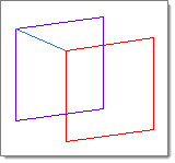
A rigid element is an element created in a space between two nodes of a model where a rigid connection is desired.

Rigid elements are element config 5 and are displayed as a line between two nodes with the letter R written at the centroid of the element.

Rigid link elements are element config 55 and are displayed as lines between the independent node and the dependent node(s) with RL displayed at the independent node of the element.

Rigid link elements can be created with dependent nodes attached to an element as a SET.  If a rigid link with a dependent node set is deleted, the associated node set is also deleted.  If the dependent node set in any panel is deleted, the connected rigid link element is also deleted.  Dependent node sets are automatically created when rigid link elements are created.  A node set created in the sets panel can be connected as a set of dependent nodes to a rigid link element independent node.

Note:Two-node rigids with a dependent node set attached are always created as rigid link elements (config 55), not as rigid elements (config 5).

Rigids can translate to RBE2 in NASTRAN or *MPC in Abaqus.


Subpanels and Inputs


The Rigids panel contains the following subpanels and command buttons:

hmtoggle_arrow1Create

Panel Inputs

Input

Action

independent: node

Pick the node that you want to be the independent node of the rigid element.

dependent: (switch)

Use the switch to choose between single node and multiple nodes.  Then, pick the node or nodes that you want to be the dependent end of the rigid element.

rigids2

single node rigidlink

rigids4

multiple nodes rigidlink

When you select multiple nodes, click the switch to change the selection mode.

nodes

Select individual nodes.

faces_edges_nodes

faces

Select all of the nodes on 2D and 3D faces.

If there are discontinuities on a 2D face, then only the nodes inbetween the discontinuities will be selected.

faces_edges_faces_nodes

2D faces ext

Select all of the nodes on a 2D face that contain discontinuities.

faces_edges_2d_face_ext_nodes

loops

Select all of the nodes on continuous free edges that make a closed loop simultaneously, such as the perimeter of a hole.

Only valid for SHELL elements.

faces_edges_loops_nodes

free edges

Select all of the nodes on free edges of elements.

If there are discontinuities on an edge, then only the nodes on the free edges inbetween the discontinuities will be selected.

Only valid for SHELL elements.

faces_edges_free_edges_nodes

free edges ext

Select all of the nodes on free edges of elements that contain discontinuities.

Only valid for SHELL elements.

faces_edges_free_edges_ext_nodes

edges

Select all of the nodes on free edges or shared edges (butt joints, L/corner joints, and T-joints) of elements.

If there are discontinuities on an edge, then only the nodes on the edge inbetween the discontinuities will be selected.

Only valid for SHELL elements.

faces_edges_edges_nodes

edges ext

Select all of the nodes on free edges or shared edges (butt joints, L/corner joints, and T-joints) of elements that contain discontinuities.

Only valid for SHELL elements.

faces_edges_edges_ext_nodes

attach dependant nodes as a set

If this is activated, a two-node rigid link element 55 with an attached node set will be created.

elem types =

Click the button to select the desired type for the new rigid element.  The exact options available depend on the current solver profile.

(dof checkboxes)

Select the degrees of freedom (DOF) for the rigid connection you want to create.

Note:When creating rigids with single dependent nodes, new rigids are created immediately upon specifying the dependent and independent nodes; ensure that the other inputs are set as you wish them to be before selecting nodes.


hmtoggle_arrow1Update

Panel Inputs

Input

Action

elems

Select the rigid elements that you wish to edit.

elem

This selector only displays when updating connectivity.  Use it to select the element that you wish to change the connectivity for.

dof

When this radio button is active, select/deselect the desired degrees of freedom (DOF) for the selected rigid elements.

connectivity

When this radio button is active, update the connectivity of a rigid link element:

Indicate which element you want to update by picking it on your model, or click elems to display the extended entity selection window.
To add or remove dependent node(s), click nodes after dependent: and click the node(s) on the model with the left mouse button to add the node(s) or with the right mouse button to remove the node(s).

The dependent node can be selected, or automatically calculated.

Click the switch to change the selection mode.

nodes

Select individual nodes.

faces_edges_nodes

faces

Select all of the nodes on 2D and 3D faces.

If there are discontinuities on a 2D face, then only the nodes inbetween the discontinuities will be selected.

faces_edges_faces_nodes

2D faces ext

Select all of the nodes on a 2D face that contain discontinuities.

faces_edges_2d_face_ext_nodes

loops

Select all of the nodes on continuous free edges that make a closed loop simultaneously, such as the perimeter of a hole.

Only valid for SHELL elements.

faces_edges_loops_nodes

free edges

Select all of the nodes on free edges of elements.

If there are discontinuities on an edge, then only the nodes on the free edges inbetween the discontinuities will be selected.

Only valid for SHELL elements.

faces_edges_free_edges_nodes

free edges ext

Select all of the nodes on free edges of elements that contain discontinuities.

Only valid for SHELL elements.

faces_edges_free_edges_ext_nodes

edges

Select all of the nodes on free edges or shared edges (butt joints, L/corner joints, and T-joints) of elements.

If there are discontinuities on an edge, then only the nodes on the edge inbetween the discontinuities will be selected.

Only valid for SHELL elements.

faces_edges_edges_nodes

edges ext

Select all of the nodes on free edges or shared edges (butt joints, L/corner joints, and T-joints) of elements that contain discontinuities.

Only valid for SHELL elements.

faces_edges_edges_ext_nodes

switch

When this radio button is active, select rigid elems whose dependent and independent nodes you wish to switch.

attach/detach set

When this radio button is active, attach or detach dependent nodes of rigid or rigid link element as a node set:

Indicate which element you want to update by picking it on your model, or click elems to display the extended entity selection window.
Activate or deactivate the Attach dependent nodes as a set check box.

If selected  elements have dependent nodes as attached nodes sets and you deactivate the attach dependent nodes as a set check box, the corresponding nodes sets are deleted and dependent nodes appear connected to the elements directly.  Two-node rigid link elements 55 are converted to rigid elements "5".

If selected elements do not have dependent nodes as attached nodes sets and you activate the attach dependent nodes as a set check box, a node set with automatically generated names is created for each selected element.  Selected rigid elements "5" are converted to two-node rigid link elements "55" with node sets attached.

elem type

When this radio button is active, select the elems that you wish to modify, then pick a new type for them.


hmtoggle_arrow1Combine

Panel Inputs

Input

Action

elems

Select the rigid elements that you wish to combine.  The rigids and rigidlinks must have the same independent node and DOFs.

If any combined rigid link elements have dependent nodes attached as a set, the resulting rigid link will also have dependent nodes attached as a set.  This set is created for a result element.  The nodes sets attached to combined elements are deleted after combining.

combine rigids with:

Toggle as needed between common independent node and any common node.


hmtoggle_arrow1Command Buttons

The following action buttons appear throughout the subpanels:

Button

Action

create

Create a new rigid link with multiple dependent nodes.  (This button does not display for rigids with single dependent nodes.)

To create a rigid element that has some or all of the degrees of freedom as an existing one, review the existing element.  This places the appropriate degrees of freedom into the panel, so that you can make any required minor changes and then create the new rigid.

reject

Undo the most recent link creation, update, or combination.

review

To review a rigid, click review and then select the rigid you want to review.

After each rigid is selected, HyperMesh will indicate which degrees of freedom (DOF1 through DOF6) are active for the element.

This function assumes that the rigid element is active and on the screen.

If a selected rigid-dependent node is attached as a node set, the name of the node set attached to the selected element is highlighted during review.

When reviewing, attach dependent nodes as a set indicates if a selected rigid element has a dependent node set attached.

update

Update the selected rigid element or elements to use the current input settings.

switch

Switch the dependent and independent nodes of the selected rigid elements.

combine

Combine the selected rigids.  The rigids and rigidlinks must have the same independent node and DOFs.

If any combined rigid link elements have dependent nodes attached as a set, the resulting rigid link will also have dependent nodes attached as a set.  This set is created for a result element.  The nodes sets attached to combined elements are deleted after combining.

return

Exit the panel.


See Also:

An Alphabetical List of HyperMesh Panels