|
»Click here to display Table of Contents«
|

FE Joints Panel |

|

|

|

|
|
FE Joints Panel |
|
|

|

|
|
»Click here to display Table of Contents«
|
FE Joints Panel |
|
|
|
|
|
FE Joints Panel |
|
|
|
|
Location: Analysis page – Safety module
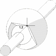
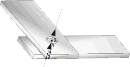
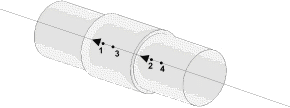
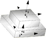
Use the FE joints panel to create, review, or update joint elements. A joint element is a definition of a connection between two rigid bodies. Joint elements store a property and orientation information.
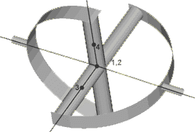
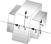
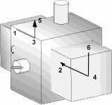
Joint elements are config 22 and are displayed with lines between the appropriate nodes and the letter J between nodes 1 and 3 of the element. The type of a joint element controls the number of nodes contained in the element. The type also controls the orientation information formats available. The type of an element CANNOT be changed or selected using the Element Types panel.
The types are as follows:
Type |
Type Name |
# nodes |
Orientation |
User Profile |
|
1 |
|
2 |
none/systems/nodes |
LS-DYNA, PAM CRASH 2G |
|
2 |
|
4 |
none/systems |
LS-DYNA |
|
3 |
|
4 |
none/systems |
LS-DYNA |
|
4 |
|
4 |
none/systems |
LS-DYNA |
|
5 |
|
4 |
none/systems |
LS-DYNA |
|
6 |
|
6 |
none/systems |
LS-DYNA |
|
7 |
|
6 |
none/systems |
LS-DYNA |
|
8 |
Ball joint |
2 |
none |
OptiStruct |
|
9 |
Fixed joint |
2 |
none |
OptiStruct |
|
10 |
Revolute joint |
2 |
node/vector/coordinates |
OptiStruct |
|
11 |
Translational1 joint |
2 |
node/vector/coordinates |
OptiStruct |
|
12 |
Cylindercal 1 joint |
2 |
node/vector/coordinates |
OptiStruct |
|
13 |
Universal joint |
2 |
node/vector/coordinates |
OptiStruct |
|
14 |
Constant_velocity joint |
2 |
node/vector/coordinates |
OptiStruct |
|
15 |
Planar joint |
2 |
node/vector/coordinates |
OptiStruct |
|
16 |
Inline joint |
2 |
node/vector/coordinates |
OptiStruct |
|
17 |
Perpendicular joint |
2 |
node/vector/coordinates |
OptiStruct |
|
18 |
Parallel axes joint |
2 |
node/vector/coordinates |
OptiStruct |
|
19 |
Inplane joint |
2 |
node/vector/coordinates |
OptiStruct |
|
20 |
Orient joint |
2 |
node/vector/coordinates |
OptiStruct |
|
21 |
Point_to_curve joint |
2 |
node/vector/coordinates |
OptiStruct |
|
22 |
Curve_to_curve joint |
2 |
node/vector/coordinates |
OptiStruct |
|
23 |
Point_to_deformable_curve joint |
2 |
node/vector/coordinates |
OptiStruct |
|
24 |
Point_to_deformable_surface joint |
2 |
node/vector/coordinates |
OptiStruct |
|
25 |
Translational_2N joint |
2 |
none/systems |
PAM CRASH 2G |
|
26 |
Revolute_2N joint |
2 |
none/systems |
PAM CRASH 2G |
|
27 |
Cylindrical_2N joint |
2 |
none/systems |
PAM CRASH 2G |
|
28 |
Universal_2N joint |
2 |
none/systems |
PAM CRASH 2G |
|
29 |
Flexion-Torsion joint |
2 |
none/systems |
PAM CRASH 2G |
|
30 |
Planar_2N joint |
2 |
none/systems |
PAM CRASH 2G |
|
31 |
General joint |
2 |
none/systems |
PAM CRASH 2G |
|
32 |
Bracket joint |
2 |
none/systems |
PAM CRASH 2G |
|
33 |
Free joint |
2 |
none/systems |
PAM CRASH 2G |
The FE Joints panel contains the following subpanels and command buttons:
Panel Inputs
|
Changing Types: Changing a spherical joint that uses orientation nodes to any other joint type causes the orientation value to be set to none and the nodes eliminated from the element, except in the case detailed below. Changing a joint type to another that requires the same number of nodes does not change the nodes. Changing a joint type to another that requires less nodes cause the extra nodes to be removed from the element. Changing a joint type to another that requires more nodes is possible under certain circumstances.
Changing Nodes: When an element’s nodes are being updated, only the nodes specified are replaced. The other are left unchanged. For example, changing a 6-noded joint's nodes and picking nodes 2 and 6 leaves nodes 1, 3, 4, and 5 the same. Nodes 2 and 6 are then updated.
Changing Properties: Properties are updated for all selected elements if the box is checked.
Changing Orientation: Changing the orientation of non-spherical joints to nodes causes the update operation to fail for that joint. The failed joint is then placed in the saved mark.
Panel Inputs
|
The following action buttons appear throughout the subpanels:
|