HyperMesh and BatchMesher

Joints Panel

Joints Panel

Previous topic Next topic Expand/collapse all hidden text  

Joints Panel

Previous topic Next topic JavaScript is required for expanding text JavaScript is required for the print function  

Location:   1D page


Use the Joints panel to create, review and update joint elements for use in an OptiStruct Multi-Body Dynamics simulation.

Note:The Joints panel is only available when the OptiStruct user profile is loaded.


Panel Usage


The Joints panel contains subpanels to create and update joints. Settings made on one subpanel do not affect any identical inputs on the other, and settings are persistent so you will not lose work by switching from one subpanel to another.

joints_panel


Subpanels and Inputs


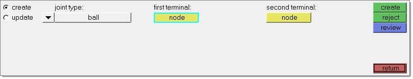
The Joints panel contains the following subpanels and command buttons:

hmtoggle_arrow1Create

Use the Create subpanel to create new joint elements.


Panel Inputs

Input

Action

joint type

Click the switch beneath joint type: and select a type from the pop-up list. There are many types to choose from:

Ball

All translations are fixed, all rotations are free.

Fixed

All translations and rotations are fixed.

Revolute

Rotation about a single selected axis is free, other rotations and translations are fixed.

Translational

Translation along a single selected axis is free, other translations and rotations are fixed.

Cylindrical

Translation along and rotation about a single selected axis is free, other translations and rotations are fixed.

Universal

Rotations about two selected perpendicular axes are free, translations and other rotations are fixed.

Constant Vel

Rotations about two selected axes are equal and opposite, translations and other rotations are fixed.

Planar

Translations on a plane defined by a selected normal vector and the rotation about that normal vector are free, out-of-plane translations and rotations are fixed.

Inline

Translation along a single selected axis and all rotations are free, other translations are fixed.

Perpendicular

Two perpendicular axes are selected that are always to remain perpendicular. Therefore rotations about both selected axes and all translations are free. Rotation about the cross-product of the two selected vectors is fixed.

Parallel Axis

Two parallel axes are selected that are always to remain parallel. Therefore rotations about the selected parallel axes and all translations are free, other rotations are fixed.

Inplane

Two perpendicular vectors are selected that describe a plane. Out-of-plane translations are fixed, all other translations and rotations are free.

Orient

All rotations are fixed, all translations are free.

Point to Curve

Defines a higher pair joint where a fixed node on a body is required to slide along a fixed curve.  The node is not allowed to lift off the curve.

Curve to Curve

Defines a higher pair joint consisting of a 3D curve fixed on one body rolling and sliding on a 3D curve fixed on a second body. The curves are required to have a unique point of contact and a common tangent at that point of contact.

Point to Deformable Curve

Defines a higher pair joint where a fixed node on a body is required to slide along a deformable curve consisting of nodes that may be attached to different bodies.

Point to Deformable Surface

Defines a higher pair joint where a fixed node on a body is required to slide along a deformable surface consisting of nodes that may be attached to different bodies.

Please refer to the OptiStruct documentation for more details on the joint entity and how to define it.

first terminal

For all joint types a first terminal node must be defined. This identifies the first constituent body for the joint and in many instances the joint’s location.

second terminal

For all joint types a second terminal node must be defined.  This identifies the second constituent body for the joint. In most instances the first and second terminals must be either coincident, along the joint axis, or on the plane of the joint.

first curve

This option only appears for higher pair joints, and allows you to select curves or surfaces to define the constraint.

second curve

This option only appears for the Curve to Curve higher pair joint, and defines the second parametric curve.

first orientation

This option only appears for joints where a first orientation vector is required. You have the option to define either a vector or a node. If the node is defined, the vector is from the first or second terminal (depending on the joint type) to the first orientation node.

second orientation

This option only appears for joints where a second orientation vector is required.  You have the option to define either a vector or a node. If the node is defined, the vector is from the first or second terminal (depending on the joint type) to the second orientation node.


hmtoggle_arrow1Update

Use the Update subpanel to alter the characteristics of existing joint elements.


Panel Inputs

Input

Action

elems

Select the joint element/elements to be updated.

joint type

Click the switch beneath joint type: and select a type from the pop-up list.  There are many types to choose from:

Ball

All translations are fixed, all rotations are free.

Fixed

All translations and rotations are fixed.

Revolute

Rotation about a single selected axis is free, other rotations and translations are fixed.

Translational

Translation along a single selected axis is free, other translations and rotations are fixed.

Cylindrical

Translation along and rotation about a single selected axis is free, other translations and rotations are fixed.

Universal

Rotations about two selected perpendicular axes are free, translations and other rotations are fixed.

Constant Vel

Rotations about two selected axes are equal and opposite, translations and other rotations are fixed.

Planar

Translations on a plane defined by a selected normal vector and the rotation about that normal vector are free, out-of-plane translations and rotations are fixed.

Inline

Translation along a single selected axis and all rotations are free, other translations are fixed.

Perpendicular

Two perpendicular axes are selected that are always to remain perpendicular. Therefore rotations about both selected axes and all translations are free. Rotation about the cross-product of the two selected vectors is fixed.

Parallel Axis

Two parallel axes are selected that are always to remain parallel. Therefore rotations about the selected parallel axes and all translations are free, other rotations are fixed.

Inplane

Two perpendicular vectors are selected that describe a plane. Out-of-plane translations are fixed, all other translations and rotations are free.

Orient

All rotations are fixed, all translations are free.

Point to Curve

Defines a higher pair joint where a fixed node on a body is required to slide along a fixed curve.  The node is not allowed to lift off the curve.

Curve to Curve

Defines a higher pair joint consisting of a 3D curve fixed on one body rolling and sliding on a 3D curve fixed on a second body. The curves are required to have a unique point of contact and a common tangent at that point of contact.

Point to Deformable Curve

Defines a higher pair joint where a fixed node on a body is required to slide along a deformable curve consisting of nodes that may be attached to different bodies.

Point to Deformable Surface

Defines a higher pair joint where a fixed node on a body is required to slide along a deformable surface consisting of nodes that may be attached to different bodies.

Please refer to the OptiStruct documentation for more details on the joint entity and how to define it.

first terminal

For all joint types a first terminal node must be defined. This identifies the first constituent body for the joint and in many instances the joint’s location.

second terminal

For all joint types a second terminal node must be defined.  This identifies the second constituent body for the joint. In most instances the first and second terminals must be either coincident, along the joint axis, or on the plane of the joint.

first curve

This option only appears for higher pair joints, and allows you to select curves or surfaces to define the constraint.

second curve

This option only appears for the Curve to Curve higher pair joint, and defines the second parametric curve.

first orientation

This option only appears for joints where a first orientation vector is required. You have the option to define either a vector or a node. If the node is defined, the vector is from the first or second terminal (depending on the joint type) to the first orientation node.

second orientation

This option only appears for joints where a second orientation vector is required.  You have the option to define either a vector or a node. If the node is defined, the vector is from the first or second terminal (depending on the joint type) to the second orientation node.


hmtoggle_arrow1Command Buttons

The following action buttons appear throughout the subpanels:

Button

Action

create:

Once all required selections have been made, click create to create the new joint entity.

review:

Click review and select a joint from the graphics area. The graphics area shows the terminal nodes of the joint while the panel displays the joint’s characteristics.

update:

Once all required selections have been made, click update to assign the new characteristics to the joint entity.

return

Exits the panel.


See Also:

An Alphabetical List of HyperMesh Panels