Location:
|
Select sph from the 1D page (LS-Dyna, RADIOSS, PAMCRASH, and Abaqus profiles).
|
|
Click Mesh > Create > SPH from the menu bar (LS-Dyna, RADIOSS, and PAMCRASH, profiles).
|
|
Click Mesh > Create > 1D Elements > SPH from the menu bar (Abaqus profile).
|
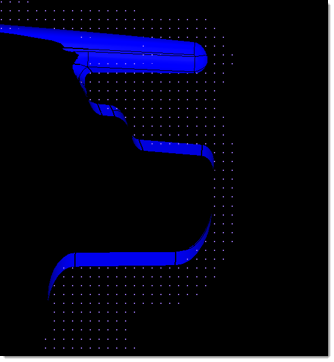
Smooth Particle Hydrodynamics (SPH) is a technique used to analyze bodies that do not have high cohesive forces among themselves and undergo large deformation, such as liquids and gases. Use the Smooth Particle Hydrodynamics panel to perform SPH analysis on a component with volume, such as airbags or fuel tanks.
In SPH Finite Point Method (SPH FPM), a given volume of the body of interest is discretized into particles, called SPH elements. These elements are node-like particles which have no geometric connectivity among themselves. Each SPH element has an effective mass. The summed mass of all particles in the filled volume of the body should be equal to the mass of the filled volume.
Subpanels and Inputs
There are no subpanels on the SPH panel. All inputs and command buttons are located on the main panel.
Panel Inputs
Input
|
Action
|
(entity selector)
|
Use the switch to choose between elems, comps, surfs, or solids.
This determines what you will pick in the graphics area to define the volume to be filled with SPH elements. Use the resulting entity selector to pick the desired entities from the model, or use the extended entity selection menu.
|
use reference
|
SPH elements are generated at the corners/face centers of the cubes which fall within the user defined criteria.
Select this option to specify which point the generation of cubes should be started.
The base point defines the starting point for cube generation, and is utilized by the mesher as a starting point.
| • | global origin. Uses (0, 0, 0) for the reference point. |
| • | local origin. Enables users to define node coordinates for the reference point. |
|
mesh orientation
|
Define the orientation of SPH elements.
| • | global system. Uses the default global system to aligns generated SPH elements. |
| • | local system. Enables users to define reference systems local to the model orientation. Generated SPH elements are aligned using the user defined local system. |
|
pitch
|
Determines the distances between each SPH particle. Thus, smaller numbers will result in more elements within the same space, but this will not affect the mass or density of the substance (gas, fluid, and so on) that he particles represent.
| • | simple cubic arranges SPH particles in groups of 8, each particle being a corner of a cube. |
| • | face centered cubic arranges the particles in groups of 14, forming the corners and the center of each face of a cube. This is similar to a hexagonal close packed (HCP) structure and is recommended for use in RADIOSS models. |
|
material density= /
filled volume mass=
|
These options allow you to specify the quantity of fluid, either by
| • | specifying its density (the total mass is then determined by the volume filled) or |
| • | specifying its total mass (volume and density is determined by the model volume filled). |
|
volume definition
|
Specifies which elements to generate SPH elements for.
| • | all. Generate SPH elements in all of the volumes in the model. |
| • | enclosed. Generate SPH elements in the volumes enclosed by the defined nodes, and ignores the remaining volumes. |
| • | Nth Largest. Enables you to specify which volumes to generate SPH elements in by defining the wrap size index in terms of volume size. To specify the largest volume, enter 1 in the index field; to specify the second largest volume, enter 2 in the index field. |
| • | exclude enclosed. Ignores the volume(s) enclosed by the defined nodes and generates SPH elements in the remaining volumes. |
|
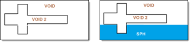
partial fill
|
Enable this checkbox to model a fluid or gas that does not completely fill the selected volume.
If enabled, perform the following steps:
| • | Toggle between percent and depth. |
| o | Percent. Percentage of the volume to fill. |
| o | Depth. Depth of the volume to fill. |
| • | Enter a percentage/depth of the volume to fill. Calculation of the volume is based on the lowest point of the model, parallel to the user defined plane. |
| • | Use the plane and vector selector to specify the direction of fill, which is generally the opposite of the direction of gravity when the filled volume is installed in the real world. |
| • | If the particle mass is filled along the correct axis, but in the wrong direction (for example from the top of a fuel tank downward) click reverse direction to fix this. |
|
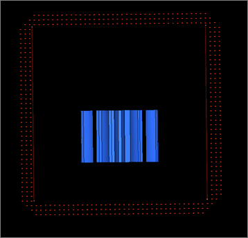
wall offset
|
Create SPH particles up to a distance that you specify.
The thickness of SPH elements is created from input. The distance between the SPH particles is driven by the pitch.
|
external to volume
|
Creates SPH particles outside of the defined volume.
Only available when wall offset is enabled. This option enables the capability to offset SPH elements from selected volume surfaces.
|
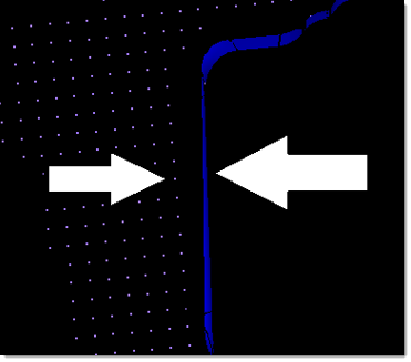
wall clearance
|
Create SPH particles from the specified distance.
This option is useful when you are trying to avoid contact of SPH elements with walls at the beginning of the solver run (1st iteration) and want the solver to run smoothly.
|
Command Buttons
The following action buttons appear:
Button
|
Action
|
create
|
Create a new SPH analysis.
|
reject
|
If the particle fill is incorrect, click reject.
| Note: | Once you exit the panel you will no longer be able to reject the fill. |
|
return
|
Exit the panel.
|
See Also:
Smooth Particle Hydrodynamics
An Alphabetical List of HyperMesh Panels


