In this tutorial, you will learn how to build 1D elements.
Model Files
This exercise uses the 1d_elements.hm file, which can be found in the hm.zip file. Copy the file(s) from this directory to your working directory.
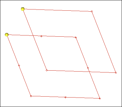
Exercise: Creating 1-D Elements
Step 1: Retrieve the model file.
| 1. | Start HyperMesh Desktop. |
| 2. | From the menu bar, click File > Open > Model. |
| 3. | In the Open Model dialog, open the 1d_elements.hm model file. |
Step 2: Create 1-D bar elements.
| 1. | Open the Bars panel by clicking Mesh > Create > 1D Elements > Bars from the menu bar. |
| 2. | Go to the bar2 subpanel. |
| 3. | In the ax, ay, and az fields, enter 0. These are the values for the bar offset. |
| 4. | Click property = and select property1. HyperMesh assigns a property to the element. |
| 5. | In the pins a and pins b fields, enter 0. These are the values for the degrees of freedom. |
| 6. | Click the orientation switch and select components. |
| 7. | In the x comp, y comp, and z comp fields, enter 1. These values define the local y-axis. |
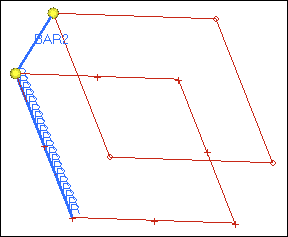
| 8. | Activate the node A selector, and select the lower node indicated in the following image. |
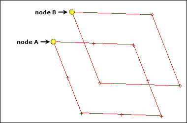
| 9. | With the node B selector now active, select the upper node indicated in the previous image. HyperMesh creates the two-noded bar element. |
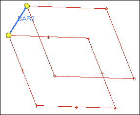
| 10. | Exit the panel by clicking return. |
Step 3: Create 1-D elements along a line.
| 1. | Open the Line Mesh panel by clicking Mesh > Create > Line Mesh from the menu bar. |
| 2. | Verify that the entity selector is set to lines. |
| 3. | Select the line indicated in the following image. |
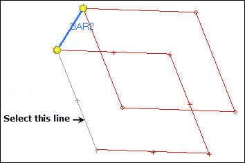
| 4. | Verify that the toggle is set to segment is whole line. |
| 5. | From the element config list, select rigid. |
| 6. | Click mesh. The Density panel opens. |
| 7. | Activate the set segment selector. |
| 8. | In the elem density = field, enter 20. |
| 9. | Click set all. HyperMesh creates rigids on the selected line. |
| 10. | Go back to the main menu by clicking return twice. |
Step 4: Create 1-D elements from the feature in the model.
| 1. | In the Model browser, turn off the display of all of the geometry in the model. |
| 2. | Turn off the display of all of the elements in the model except for the elements in the feature_elements component. |
| 3. | Open the Features panel by clicking Mesh > Check > Components > Features from the menu bar. |
| 4. | Verify that the entity selector is set to comps. |
| 5. | Click comps >> feature_elements. |
| 7. | In the feature angle = field, enter 30. |
| 8. | Select the ignore normals check box. |
| 9. | Verify that the create toggle is set to plot elements. |
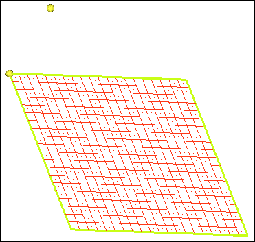
| 10. | Click features. HyperMesh creates the plot elements as green edge lines. |
| 11. | Exit the panel by clicking return. |
See Also:
HyperMesh Tutorials


