In this tutorial, you will:
| • | Learn how to mesh all of the surfaces at once, specifying different element sizes and element types |
| • | Practice changing the element density along surface edges |
| • | Practice checking element quality and changing the mesh pattern by changing the mesh algorithm |
| • | Learn how to preview the mesh on all the unmeshed surfaces |
| • | Practice changing the element type and node spacing (biasing) along surface edges |
| • | Learn how to remesh surfaces |
The optimal starting point for creating a shell mesh for a part is to have geometry surfaces defining the part. The most efficient method for creating a mesh representing the part includes using the Automesh panel and creating a mesh directly on the part’s surfaces.
Model Files
This exercise uses the channel.hm file, which can be found in the hm.zip file. Copy the file(s) from this directory to your working directory.
Exercise
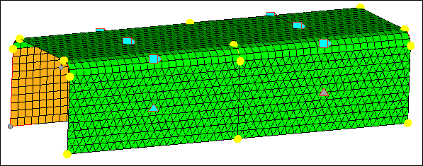
Step 1: Open and view the model file, channel.hm.
| 1. | Start HyperMesh Desktop. |
| 2. | From the menu bar, click File > Open > Model. |
| 3. | In the Open Model dialog, open the channel.hm model file. |
| 4. | Observe the model using the different visual options available in HyperMesh (rotation, zooming, etc.). |
Step 2: Mesh all the part’s surfaces at once using an element size of 5 and the mixed element type (quads and trias).
| 1. | To open the AutoMesh panel, click Mesh > Create > 2D AutoMesh from the menu bar, or press F12. |
| 2. | Go to the size and bias subpanel. |
| 3. | Verify that the entity selector is set to surfs. |
| 4. | Click surfs >> displayed. |
| 5. | In the element size= field, enter 5. |
| 6. | Set the mesh type: to mixed. |
| 7. | Set the active mesh model to interactive. |
| 8. | Set the first toggle to elems to current comp. |
| 9. | Click mesh. HyperMesh opens the density subpanel in the meshing module. The model displays node node seeding and a number on each surface edge. |
| Note: | The number displayed in the graphics area is the number of elements that were created along the edge. |
| 10. | To accept the mesh as the final mesh, click return. |
At this point, you could be done using the Mesh panel to mesh the part. The mesh quality is very good. However, you will remain in the meshing module to perform the next steps, which demonstrate how to use various subpanels to interactively control the creation of the mesh.
Step 3: Delete the mesh.
| 1. | To open the Delete panel, click  on the Collectors toolbar, or press F2. on the Collectors toolbar, or press F2. |
| 2. | Set the entity selector to elems. |
| 5. | To go back to the AutoMesh panel, click return. |
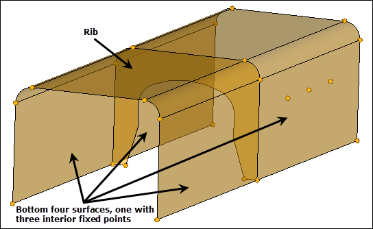
Step 4: Mesh the surface having three fixed points interior to its surface.
In this step, you should be in the AutoMesh panel, size and bias subpanel.
| 1. | Leave all options in the subpanel as they are. |
| 2. | Select the surface that has three fixed points interior to its surface indicated in the following image. |
| 3. | Click mesh. HyperMesh opens the meshing module. |
| 4. | Preview the generated mesh. |
Step 5: Fit only the surface being meshed to the graphics area.
| 1. | To fit the surface to the graphics area, click f or click local view >> fill in the density subpanel. |
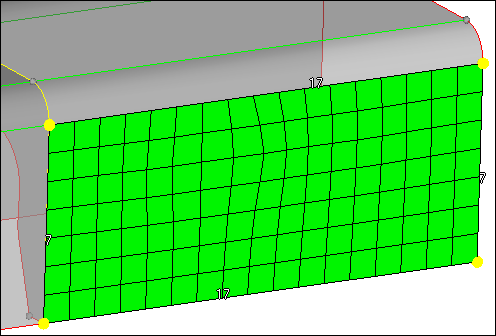
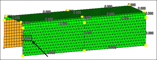
Step 6: From the graphics area, specify a new element density along surface edges.
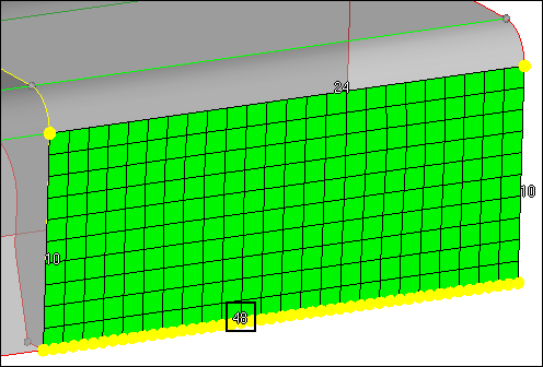
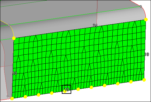
| 1. | From the density subpanel, activate the adjust: edge selector. |
| 2. | To change the element density number of the edge indicated in the following image from 24 to 48: |
| • | Left-click on the edge’s element density number to increase it by one, or right-click on the element's density number to decrease it by one. |
or
| • | Click and hold the mouse pointer on the edge’s element density number and drag your mouse up to increase the number or down to decrease the number. |
| 3. | Click mesh. HyperMesh updates the preview mesh based on the change. |
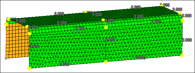
Step 7: From the density subpanel, specify a new element density along surface edges.
In this step, you should still be in the density subpanel.
| 1. | In the elem density= field, enter 10. |
| 2. | Activate the set: edge selector. |
| 3. | Select the element density number of the edge indicated in the following image to change its value to 10. |
| 4. | Click mesh. HyperMesh updates the preview mesh based on the change. |
| 5. | Click set all to. HyperMesh changes all of the edge's densities to 10. |
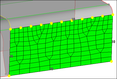
| 6. | Click mesh. HyperMesh updates the preview mesh based on the change. |
Step 8: From the density subpanel, specify a new element size to adjust element densities along surface edges.
| 1. | In this step, you should still be in the density subpanel. |
| 2. | In the elem size= field, enter 7. |
| 3. | Activate the calculate: edge selector. |
| 4. | Select the element density number of the edge indicated in the following image to calculate it based on an element size of 7. HyperMesh calculates the new number to create elements as close as possible to 7. |
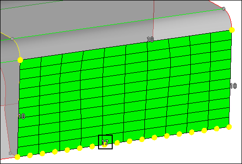
| 5. | Click mesh. HyperMesh updates the preview mesh based on the change. |
| 6. | Click recalc all. HyperMesh calculates and changes all of the edge's densities based on an element size of 7. |
| 7. | Click mesh. HyperMesh updates the preview mesh based on the change. |
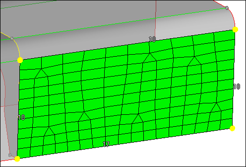
Step 9: Change all edge element densities to reflect the initial element size of 5.
| 1. | In the elem size= field, enter 5. |
| 3. | Click mesh. HyperMesh updates the preview mesh based on the change. |
| 4. | To accept the mesh and go back to the size and bias subpanel, click return. |
Step 10: Preview a mesh of the channel’s rib.
In this step, you should still be in the Mesh panel, size and bias subpanel.
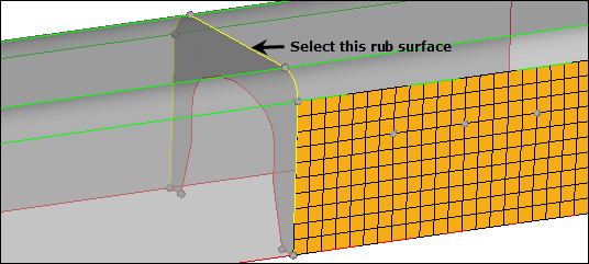
| 1. | With the entity selector active and set to surfs, select the rib surface in the middle of the part as indicated in the following image. |
| 2. | Leave all options in the menu panel set as they are. |
| 3. | Click mesh. HyperMesh opens the meshing module and generates the preview mesh. |
| 4. | To fit the rib's surface to the graphics area, click local view >> rear. |
Step 11: Check the quality of the rib’s preview mesh.
| 1. | Go to the checks subpanel. |
| 2. | To identify all of the elements that have an aspect ratio greater than 5, click aspect. None of the elements fail the check, and the status bar reads, "Maximum aspect ratio found is equal to 1.75". |
| 3. | In the jacobian < field, enter 0.8. |
| 4. | To identify all of the elements that have a jacobian less than 0.8, click jacobian. HyperMesh identifies several elements that fail the check and outlines them in red. The status bar reads, "Minimum jacobian found is equal to 0.75." |
| 5. | Verify that none of the elements have a jacobian less than 0.7. |
| 6. | Under quads, enter 45 in the min. angle < field. |
| 7. | Click min angle. The minimum interior angle found among all of the quad elements is 46.46. |
| 8. | Under quads, enter 135 in the max. angle > field. |
| 9. | Click max angle. The maximum interior angle found among all of the quad elements is 136.58. |
Step 12: Change the rib’s mesh pattern by changing the mesh method used for its surface.
| 1. | Go to the mesh style subpanel. The edge's element density numbers have disappeared, and there is now a small icon interior to the rib's surface. This icon indicates that HyperMesh is currently using the free (unmapped) mesh method to mesh the surface. |
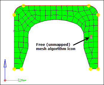
| 2. | Under mesh method, use the switch to select map as rectangle. |
| 3. | Under mesh method, click set all. The icon changes to reflect the new mesh method. |
| 4. | Click mesh. HyperMesh updates the preview mesh based on the change. |
Step 13: Check the quality of the rib’s preview mesh again.
| 1. | Go the checks subpanel. |
| 2. | Check for elements having an aspect ratio greater than 5. |
Highest value reported is _____.
| 3. | Check for elements having a jacobian less than 0.7. |
Lowest value reported is _____. In this case, the free (unmapped) mesh has a better jacobian than the map as rectangle mesh.
| 4. | Check for quad elements having a min angle less than 45. |
Smallest value reported is _____.
| 5. | Check for quad elements having a max angle greater than 135. |
Highest value reported is _____.
Step 14: Change the rib’s mesh method back to free (unmapped).
| 1. | Go to the mesh style subpanel. |
| 2. | Under mesh method, use the switch to select free (unmapped). |
| 3. | Under mesh method, click set all. |
| 4. | Click mesh. HyperMesh updates the preview mesh based on the change. |
| 5. | To accept the mesh as final and go back to the Mesh panel, click return. |
Step 15: Preview a mesh of all displayed, unmeshed surfaces.
In this step, you should still be in the Mesh panel, size and bias subpanel.
| 1. | On the standard toolbar, click  . . |
| 2. | Accept all the default values. |
| 3. | Click failed. The status bar reads "There are no surfaces with meshing errors". |
| Note: | This is correct; all of the surfaces you selected to mesh so far have a mesh on them. |
| 4. | To identify and select all of the displayed, unmeshed surfaces, click unmeshed. |
| 5. | Click mesh. HyperMesh opens the meshing module and generates the preview mesh. |
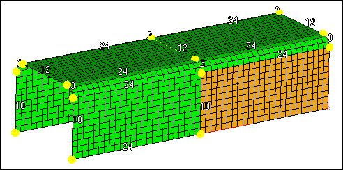
Step 16: Change the element type for some surfaces to trias.
| 1. | Go to the mesh style subpanel. |
| 2. | Under elem type, click toggle surf. HyperMesh displays  interior to each surface, which indicates that the mixed element type (quads and trias) is currently being used to mesh the surface. interior to each surface, which indicates that the mixed element type (quads and trias) is currently being used to mesh the surface. |
| 3. | Under elem type, use the switch to change the mesh type to trias. |
| 4. | Under elem type, activate the set surf selector. |
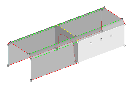
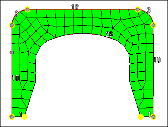
| 5. | On the two surfaces indicated in the following image, left-click on , to set their element type to trias ( ). ). |
| 6. | Click mesh. HyperMesh updates the preview mesh based on the change. |
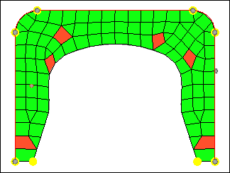
Preview of mesh with tria element type for two surfaces
Step 17: Adjust the node spacing on surface edge (biasing).
| 1. | Go to the biasing subpanel. The bias intensity number on each surface edge is 0.000, which is the default number. |
| 2. | Leave the bias style set to linear. |
| Note: | This style corresponds to the positive slope of a straight line over the interval [0,1] of the real line. For a positive bias intensity, smaller elements are at the start of the edge. |
| 3. | Verify that the adjust: edge selector is active. |
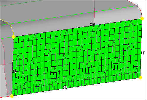
| 4. | To change the biasing intensity number of the edge indicated in the following image from 0.0 to 3.0: |
| • | Left-click on the edge’s biasing intensity number to increase it by 0.1, or right-click on the edge's biasing intensity number to decrease it by 0.1. |
or
| • | Click and hold the mouse pointer on the edge’s biasing intensity number and drag your mouse up to increase the number or down to decrease the number. |
| 5. | Click mesh. HyperMesh updates the preview mesh based on the change. |
| 6. | In the intensity= field, enter 10. |
| 7. | Activate the calculate: edge selector. |
| 8. | Click the same edge’s biasing intensity number to change it to 10. |
| 9. | Click mesh. HyperMesh updates the preview mesh based on the change. |
| 10. | Set the bias style to bellcurve. This bias style distributes nodes along the edge in a pattern that is symmetric across the midpoint of the edge. |
| Note: | For a positive biasing intensity, the smaller elements are at the start and end of the edge. |
| 11. | Activate the set: edge selector. |
| 12. | On the same edge, click  to change it from the linear bias style to the bellcurve ( to change it from the linear bias style to the bellcurve ( ) bias style. ) bias style. |
| 13. | Click mesh. HyperMesh updates the preview mesh based on the change. |
| 14. | To accept the final mesh and go back to the Mesh panel, click return. |
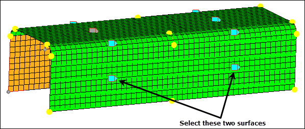
Step 18: Remesh the channel’s bottom two surfaces.
In this step, should still be in the Mesh panel, size and bias subpanel.
| 1. | Switch the mesh mode from interactive to automatic. |
| Note: | This mode is not interactive, therefore it does not take you to the meshing module. Rather, it meshes surfaces using only the basic parameters of the AutoMesh panel. Use Interactive mode to remesh the surfaces if you require the different options to control the created mesh. |
| 2. | Verify that the entity selector is active and set to surfs. |
| 3. | Select the two surfaces indicated in the following image. |
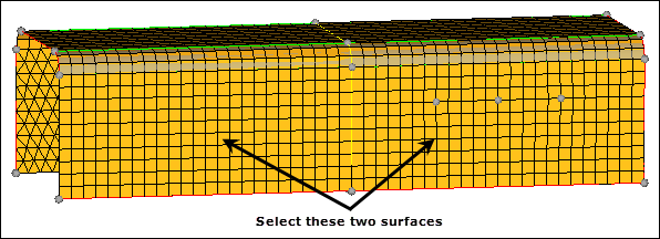
| 4. | In the element size = field, enter 10. |
| 5. | Click mesh. HyperMesh deletes the existing mesh on the selected surfaces and creates a new mesh. |
| 6. | Observe the resulting quad mesh on the remeshed surfaces. |
| Note: | Connectivity was maintained with the surrounding, smaller mesh. This is because the break connectivity option was not used. |
| 7. | To exit the panel, click return. |
Step 19 (Optional): Save your work.
Meshing of the channel part is complete. Now is a good time to save the model.
| 1. | From the menu bar, click File > Save > Model. |
See Also:
HyperMesh Tutorials


