In this tutorial, you will go through the full set up of a PERMAS analysis. You will:
| • | Organize existing elements into HyperMesh component collectors |
| • | Create materials and elemental properties and assign both to elements and sets |
| • | Create beam and spring elements |
| • | Apply loads and boundary conditions |
| • | Organize the components, loads and boundary conditions into $LOADING and $CONSTRAINTS variants |
| • | Specify contacts and contact properties |
| • | Define a load history with the $NNLOAD card |
Model Files
This tutorial uses the permastube_clamping.hm file, which can be found in <hm.zip>/interfaces/permas/. Copy the file(s) from this directory to your working directory.
Exercise
Step 1: Load the PERMAS user profile and the model
Complete the steps below to load the PERMAS user profile and the model:
| 1. | Open HyperMesh Desktop. |
| 2. | In the User Profile dialog, set the user profile to Permas. |
| 3. | From the menu bar, click File > Open > Model. |
| 4. | In the Open Model dialog, open the permastube_clamping.hm file. |
| Note: | This file contains pre-defined model data. Use this file in the following exercises. |
Step 2: Create a PERMAS $COMPONENT and $SYSTEM
As a first recommended step for each model set up in the PERMAS user profile, you should create a component and a system card. If this is not done, a warning message is displayed in the message bar on export. Currently only one component and system per model is supported in HyperMesh.
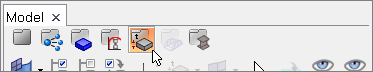
| 1. | From the menu bar, click Setup > Create > Control Cards. |
| 2. | In the Card Image dialog, click COMPONENT. |
| 3. | In the Name field, enter comp1. |
| 4. | Click return to create the card and close the card image. |
| 6. | In the Name field, enter sys1. |
| 7. | Click return to create the card and exit the card image. |
| 8. | Click return again to close the Card Image dialog. |
Step 3: Create a component collector
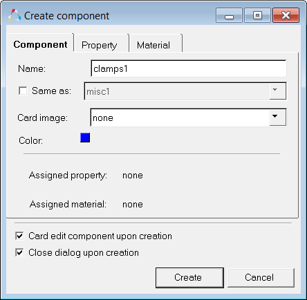
| 1. | In the Model browser, right-click and select Create > Component from the context menu. |
| 2. | In the Create Component dialog: |
| • | For Name, enter clamps1. |
| • | Select a color for the component. |
| • | Leave Card image set to none. |
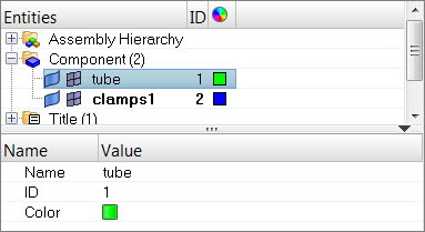
Step 4: Organize the elements
| 1. | From the menu bar, click Mesh > Organize > Elements > To Component. |
| 2. | Select one element on one side of the clamp. |
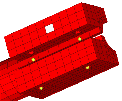
| 3. | In the Organize panel, click elems >> by attached. The entire side of the clamp becomes selected. |
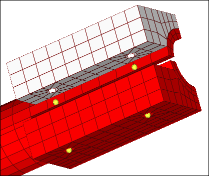
| 4. | Select the elements on the other side of the clamp. |
| 5. | In the dest component = field, ensure that clamps1 is entered. |
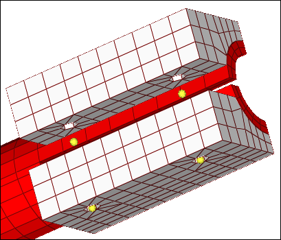
| 6. | Click move. HyperMesh organizes the selected elements into the clamps1 component. |
| 7. | Click return to exit the panel. |
| 8. | In the Model browser, Component folder, click misc1. The Entity Editor opens and displays the component's card data. |
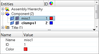
| • | Click the color box, and select a new display color for the component. |
Step 5: Creating material and elemental properties
In this step you will create two materials and a solid property for the already existing elements. You will also assign the property and the materials to the previously created components. Assigning a property/material to a component is equivalent to a property to set assignment in PERMAS. For 2D and 3D elements, it is currently the only way of property assignment.
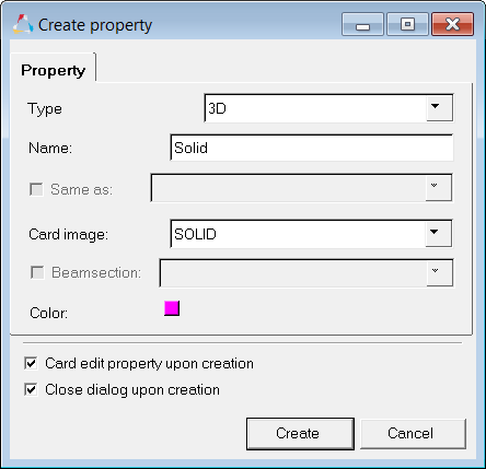
| 1. | In the Model browser, right-click and select Create > Property from the context menu. |
| 2. | In the Create Property dialog: |
| Note: | The type selection is helpful when you review your model in the Model browser (property or material view). Even if you do not select a type at this point, it will still display as the correct type. Selecting the type only prefilters the card images for you in this dialog. |
| • | Set Card image to SOLID. |
| • | Select the Card edit property upon creation checkbox. |
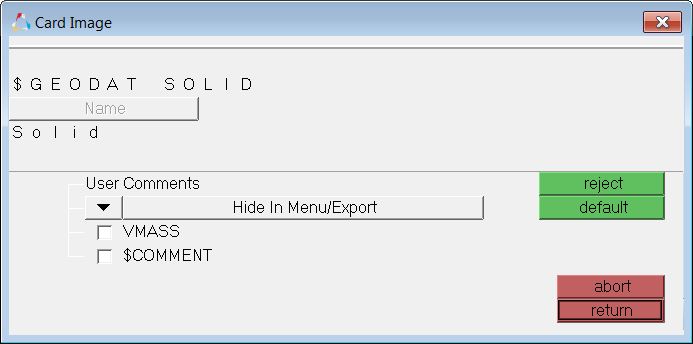
| • | Click Create. The card image for the property you just created opens. |
| 3. | When finished, click return to close the card image. |
| 4. | In the Model browser, right-click and select Create > Material from the context menu. |
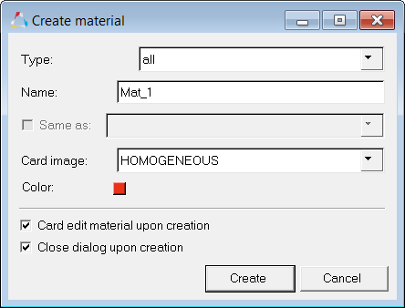
| 5. | In the Create material dialog: |
| • | Set Card image to HOMOGENEOUS. |
| • | Select the Card edit material upon creation checkbox. |
| • | Click Create. The card image for the material you just created opens. |
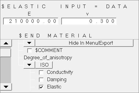
| • | Select the Elastic checkbox. |
| • | In the E (elasticity modulus field) field, enter 210000. |
| • | In the v (poisson’s ratio) field, enter 0.3. |
| • | Click return to close the card image. |
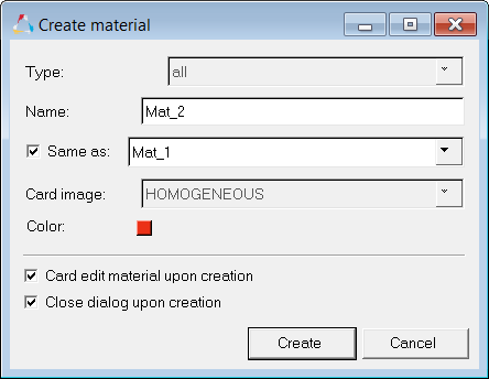
| 7. | In the Model browser, right-click and select Create > Material from the context menu. |
| 8. | In the Create material dialog: |
| • | Select the Same as checkbox to apply the same characteristics from the Mat_1 material to the Mat_2 material. |
| • | Click Create. The card image for the material you just created opens. |
| 9. | Because Mat_2 has the same characteristics as Mat_1, the Elastic checkbox is already selected and the values should already be entered in the E and v fields. Change E to 7000 and v to 0.330. |
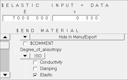
| 10. | Click return to close the card image. |
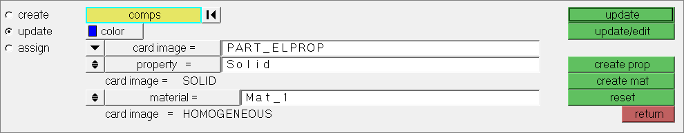
| 11. | On the Collectors toolbar, click  . The Components panel opens. . The Components panel opens. |
| 12. | Go to the update subpanel. |
| 14. | Select the component, clamps1. |
| 16. | Click Card image, and select PART_ELPROP. |
| 17. | Set the property/no property toggle to property. |
| 18. | Click property=, and select solid. |
| 19. | Set the material/no material toggle to material. |
| 20. | Click material=, and select Mat_1. |
| 22. | In the Model browser, Component folder, right-click on clamps1 and select Card Edit from the context menu. The card image opens, and the name of the component, property, and material you assigned is shown. |
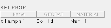
| 23. | Click return to close the card image. |
| 24. | Edit the tube component so that the card image is set to Part_ELPROP, and the Solid property and Mat_2 material are assigned. |
| 25. | Click Update to complete the changes. |
Step 6: Create the Beam elements
In this section of the tutorial you will learn how to create beam elements and assign a property to individual elements during creation. In comparison to 2D and 3D elements, you can assign mutually exclusive properties to elements or sets (components).
| 1. | In the Model browser, right-click and select Create > Component from the context menu. |
| 2. | In the Create component dialog: |
| • | Clear the Card edit component upon creation checkbox. |
| 3. | In the Model browser, right-click and select Create > Property from the context menu. |
| 4. | In the Create property dialog: |
| • | Select the Card edit property upon creation checkbox to edit the property's card data upon creation. |
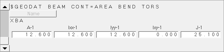
| 5. | In the card image, enter the following parameters: |
| 6. | Click return to exit the panel. |
| 7. | Open the Bars panel by clicking Mesh > Create > 1D Elements > Bars from the menu bar. |
| 8. | Set orientation selector to z-axis. |
Note: Because HyperMesh is a generic preprocessor, you have to provide an orientation vector to create the element, although this vector does not go anywhere in the PERMAS deck. For beams, use the node option in the same panel where a direction vector needs to be defined.
| 9. | Click property =, and select XBA. |
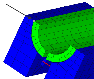
| 10. | Using the node A selector, select the node on the top of one side of the clamp. |
| 11. | Using the node B selector, select the node in the middle of the clamp that is closest to the node you selected as node A. The beam is created automatically. |
| Tip: | You may need to zoom in on the model to properly select the the node in the middle of the clamp which is closest to the node you selected as node A. |
| 12. | Repeat steps 6.17 and 6.18 to connect the lower node in the middle of the clamp with the node on the opposite, outer side. |
| 13. | Repeat steps 6.17 – 6.19 on the other side of the clamp. |
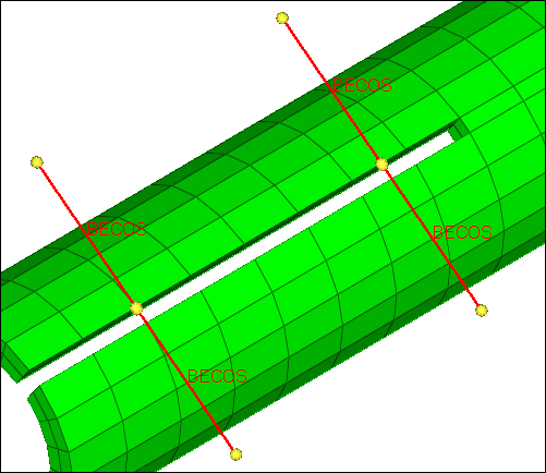
| 14. | In the Model browser, Component folder, right-click on clamps1 and select Hide from the context menu to see the four sets of bars connecting the six nodes. |
| 15. | In the Model browser, click  (property view) to display the elements in the color of the property that has been assigned to them. (property view) to display the elements in the color of the property that has been assigned to them. |
| Note: | This is a good way to ensure that you have assigned the correct property to the elements. |
| 16. | In the Model browser, click  (model view) to return to the default display settings. If necessary, right-click on the clamps1 component and select Show to display the clamps again. (model view) to return to the default display settings. If necessary, right-click on the clamps1 component and select Show to display the clamps again. |
| 17. | Click return to exit the panel. |
Step 7: Create the Spring elements
In this step you will create a spring element similar to the way you created the beam elements, and you will change the element type used when elements are created. You will use the coincident picking mechanism to help you precisely select nodes, which is useful in cases where entities (for example nodes and elements) are close to each other.
| 1. | In the Model browser, right-click and select Create > Component from the context menu. |
| 2. | In the Create component dialog: |
| • | For Name, enter Springs. |
| • | Set Card image to PART_ELPROP. |
| • | Clear the Card edit component upon creation checkbox. |
| Note: | Springs should now be your current component collector, which ensures that newly created elements are put into this collector. |
| 3. | Open the Element Type panel by clicking Mesh > Assign > Element Type from the menu bar. |
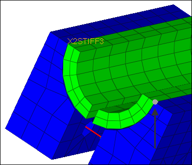
| 5. | Click spring =, and select X2STIFF3. |
| 6. | Click return to exit the panel. |
| 7. | From the menu bar, click Preferences > Graphics. |
| 8. | In the Graphics panel, select the coincident picking checkbox. |
| Note: | Coincident picking enables you to select one or more nodes which reside very close to each other. During node selection, you will have more control. See the online help for the graphics subpanel for more information. |
| 10. | In the Model browser, right-click and select Create > Property from the context menu. |
| 11. | In the Create property dialog: |
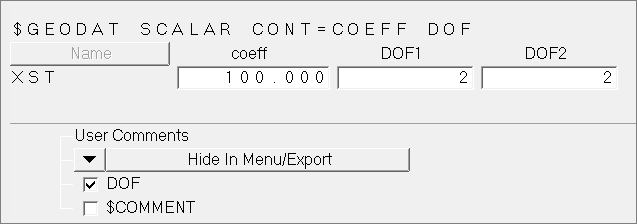
| • | Set Card image to SCALAR. |
| • | Select the Card edit property upon creation checkbox. |
| • | Click Create to create the property and edit the card. |
| • | Select the DOF checkbox to enable the degrees of freedom at the first and second node. |
| • | In the coeff field, enter 100. |
| • | In the DOF1 and DOF2 fields, enter 2. |
| 13. | Open the Springs panel by clicking Mesh > Create > 1D Elements > Springs from the menu bar. |
| 14. | Click property =, and select XST. |
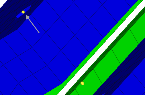
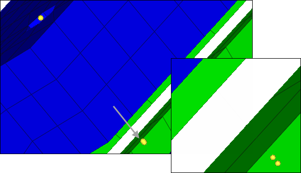
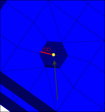
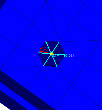
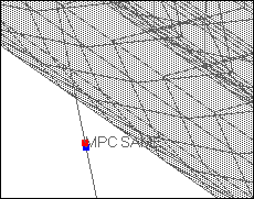
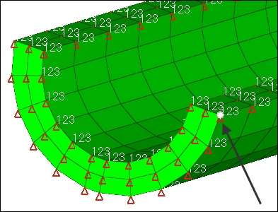
| 15. | Using the node selector, select the node shown in the image below. The coincident picking tool appears, and displays two nodes. |

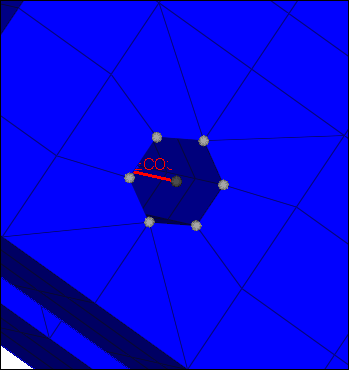
| 17. | Using the node selector, click the same node. |
| 18. | Using the coincident picking tool, click the bottom node. HyperMesh creates a spring. |

| 19. | Repeat steps 7. 25 and 7.28 to select the same nodes on the other side of the model. |
| 20. | When finished, click return to exit the panel. |
Step 8: Create Multi-Point Constraints
In this step, you will create two different types of multi point constraints. In order to switch their display on and off separately, you will create a component collector for each type. Because MPCs do not need a property assignment in HyperMesh, no card image ($ELPROP) is needed for these components.
| 1. | In the Model browser, right-click and select Create > Component from the context menu. |
| 2. | In the Create component dialog: |
| • | For Name, enter MPC_Rigids. |
| • | Clear the Card edit component upon creation checkbox. |
| Note: | This collector will be used to organize MPC elements created later in this step. |
| 3. | Open the Rigids panel by clicking Mesh > Create > 1D Elements > Rigids from the menu bar. |
| 4. | Set the dependent switch to multiple nodes. |
| 5. | Clear the dof4, dof5 and dof6 checkboxes. |
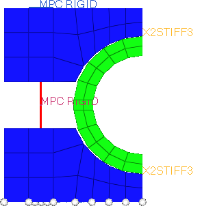
| 6. | Using the independent node selector, select one of the nodes at the end of the beam elements created in Step 6. |
| 7. | Using the dependent node selector, select the nodes surrounding the first node. |
| 9. | Repeat steps 8.9 - 8.11 to create elements for the other three ends of the beam elements. |
| 10. | When finished, click return to exit the panel. |
| 11. | Open the Utility menu by clicking View > Browsers > HyperMesh > Utility from the menu bar. |
| 12. | In the Utility menu, click Disp. |
| 13. | Click Clear Temp Nodes. |
| 14. | In the Model browser, right-click and select Create > Component from the context menu. |
| 15. | In the Create component dialog: |
| • | For Name, enter MPC_Same. |
| 16. | Open the Element Type panel. |
| 17. | Click rigid =, and select MPC SAME. |
| 18. | Click return to close the panel. |
| Note: | MPC_Same should now be your current component collector. If not, right-click on MPC_Same, in the Model browser, and select Make Current from the context menu. |
| 19. | Open the Rigids panel. A MPC Same rigid will be used to connect the two beams created in Step 6, where there is a small gap between each vertical section. You will use the Rigids panel to connect these two sections with a MPC Same rigid. |
| 20. | Select all of the DOF checkboxes, except dof2. This one is set free for the pretension load which is applied later in the tutorial. |
| 21. | Set the dependent switch to single node. |
| 22. | Using the independent node selector, select the inner end of one of the beams. |
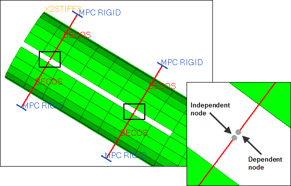
| 23. | Using the dependent node selector, select the inner end of the other beam. The MPC Same rigid is created. |
| 24. | Click return to close the panel. |
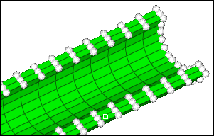
Step 9: Set definition
In this step you will create sets that will later be used for contact definition. The sets that need to be created include:
| • | SET_1: lower edge of the split portion of the tube |
| • | SET_2: upper edge of the split portion of the tube |
| • | SET_11: lower node of 1st bolt connection |
| • | SET_12: upper node of 1st bolt connection |
| • | SET_21: lower node of 2nd bolt connection |
| • | SET_22: upper node of 2nd bolt connection |
| • | Clamps: nodes of the contact surfaces at the clamps to the tube |
| 1. | In the Model browser, View folder, right-click on set_def and select Show from the context menu. |
| 2. | From the menu bar, click Tools > Create > Sets. The Sets panel opens. |
| 3. | In the name field, enter SET_1. |
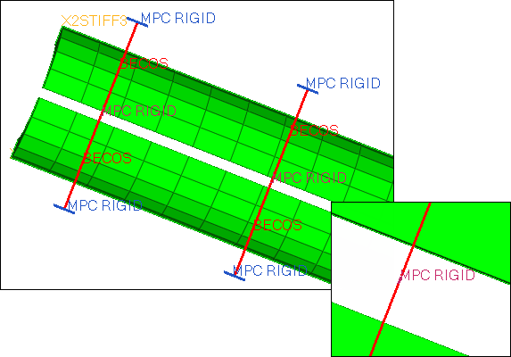
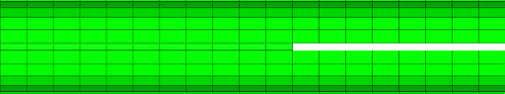
| 4. | While pressing SHIFT, draw a box around the lower edge of the split portion of the gap. All nodes within this section highlight. |
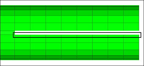
| 5. | Click create. HyperMesh organizes all of the highlighted nodes into SET_1. |
| 6. | In the Model browser, Component folder, turn on the display of Beam and MPC Same. |
| 7. | Repeat steps 9.3 – 9.5 to create SET_2, SET_11, SET_12, SET_21, and SET_22 using the definitions above. |
Use the following parameters to help you create the sets:
| • | SET_2 – Select the top set of nodes on the opening that was selected in step 4. |
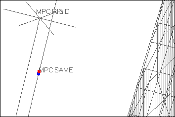
| • | SET_11 – Zoom in on the MPC SAME rigid, and select one node on the bottom of the first MPC SAME rigid created in Step 7. |
| • | SET_12 – Zoom in on the MPC SAME rigid, and select one node on the top of the first MPC SAME rigid created in Step 7. |
| • | SET_21 – Zoom in on the MPC SAME rigid, and select one node on the bottom of the second MPC SAME rigid created in Step 7. |
| • | SET_22 – Zoom in on the MPC SAME rigid, and select one node on the top of the second MPC SAME rigid created in Step 7. |
| 7. | In the Model browser, Component folder, right-click on clamps1 and select Isolate Only from the context menu. |
| 8. | On the Standard Views toolbar, click  (XY Top Plane View). (XY Top Plane View). |
| 9. | From the menu bar, click Tools > Create > Sets. |
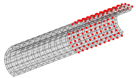
| 10. | In the name field, enter Clamps. |
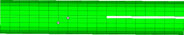
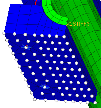
| 11. | Click nodes >> by window. |
| 12. | Draw a box to select the nodes indicated in the image below. |
| 13. | Click create. HyperMesh creates the set. |
| 14. | Click return to close the panel. |
| Tip: | When you have a large amount of sets, use the Set browser to create sets. |
Step 10: Creating a surfaces from solid elements
The surface definition and the sets from above will be used later for contact definition.
| 1. | In the Model browser, Component folder, right-click on Tube and select Isolate Only from the context menu. |
| 2. | Open the Contact Surfaces panel by clicking BCs > Create > Contact Surfaces from the menu bar. |
| 3. | Go to the solid faces subpanel. |
| 4. | In the name field, enter Surf_tube. |
| 5. | Click card image =, and select $SURFACE. |
| 6. | Set the switch to entities. |
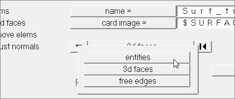
| 7. | Click elems >> by collector. |
| 8. | Select the component, tube. |
| 10. | Using the nodes selector, select two nodes on the tube component. These nodes should be on one solid element, diagonal from each other. |
| Note: | These nodes will be used to specify the faces of the solids to be taken into account for this surface creation. |
| 11. | Click create. HyperMesh creates the contact surface. |
| 12. | Click return to exit the panel. |
Step 11: Define the contact partners using $CONTACT
In this analysis, four contacts will be established.
Contact name
|
Type
|
Master
|
Slave
|
Bolt_1
|
Node to Node
|
SET_11
|
SET_12
|
Bolt_2
|
Node to Node
|
SET_21
|
SET_22
|
Gap
|
Node to Node
|
SET_1
|
SET_2
|
Tube_clamps
|
Surface to Node
|
Surf_Tube
|
Clamps
|
| 1. | Open the Interfaces panel by clicking BCs > Create > Interfaces from the menu bar. |
| 2. | Go to the create subpanel. |
| 3. | In the name field, enter tube_clamps. |
| 4. | Click type =, and select CONT_SURFACE_NODE to create a surface to node contact |
| 5. | Choose a color for the interface. |
| 7. | Go to the add subpanel. |
| 8. | Set the master switch to csurfs. |
| 9. | Using the contactsufs selector, select surf_tube. |
| 11. | Set the slave switch to sets. |
| 12. | Using the sets selector, select Clamps. |
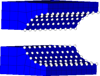
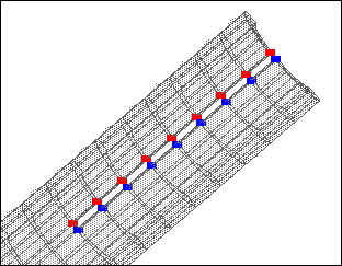
| 14. | Click review. You should now be able to see if you have set up master and slave surfaces correctly for your contact definition. Master surfaces display in blue, and slaves display in red. If one (or both) do not display, then you might have missed clicking update. If this happens, select the missing entity (master or slave) again and click update. |
| 15. | Click return to close the panel. |
| 16. | In the Model browser, Component folder, turn on the display of Beam, MPC Rigid and MPC Same. |
| 17. | From the menu bar, click BCs > Create > Interfaces. |
| 18. | Go to the create subpanel. |
| 19. | In the name field, enter Bolt_1. |
| 20. | Click type =, and select CONT_NODE_NODE for a node to node contact. |
| 21. | Choose a color for the interface. |
| 23. | Go to the add subpanel. |
| 24. | Set the master switch to sets. |
| 25. | Using the sets selector, select SET_11. |
| 27. | Set the slave switch to sets. |
| 28. | Using the sets selector, select SET_12. |
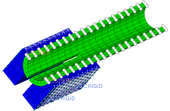
| 31. | Rotate the model to view the interface. |
| 32. | Click return to close the panel. |
| 33. | Create the Bolt_2 interface, with the following criteria: |
| • | Interface type – CONT_NODE_NODE |
| 34. | Isolate the display of the tube component, and create the interface named Gap, with the following criteria: |
| • | Interface type – CONT_NODE_NODE |
| 35. | In the Model browser, Group folder, right-click on Gap and select Card Edit from the context menu. |
| 36. | In the card image of the $CONTACT card, click CONTSYS and select DIRECT. |
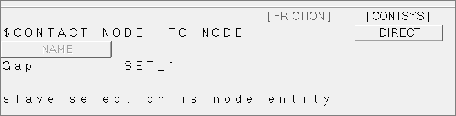
| 38. | Repeat steps 11.35 – 11.36 for the Bolt_1 and Bolt_2 interfaces. |
Step 12: Create the boundary conditions
In this step you will create the constraints applied to this simulation, and group them into one load collector named Boundary. Later you will create a $CONSTRAINTS variant (load step in HyperMesh) and attach the load collector with the previously created contact constraints.
| 1. | In the Model browser, right-click and select Create > Load Collector from the context menu. |
| 2. | In the Create Load Collector dialog: |
| • | For Name, enter Boundary. |
| • | Select a color for the load collector. |
| • | Set the Card image to SUPPRESS. |
| 3. | On the Standard Views toolbar, click (XY Top Plane View). |
| 4. | Open the Constraints panel by clicking BCs > Create > Constraints from the menu bar. |
| 5. | Clear the dof4, dof5 and dof6 checkboxes. |
| 6. | Verify that the Clamps1 component is displayed. |
| 7. | While pressing SHIFT, draw a box around the bottom row of elements to select the nodes. |
| 8. | Rotate the model so that the underside of the bottom clamp is shown. |
| 9. | Right-click on the nodes around the MPC Rigids to deselect them. |
| 10. | Deselect the nodes surrounding the other MPC Rigid on this side of the clamp as well. |
| 12. | In the Model browser, Component folder, display tube. |
| 13. | In the size field, enter 1.0 to reduce the size of the constraints in the graphics area. |
| 14. | While pressing SHIFT, draw a box around the far end of the tube to select those nodes in order to include them in the constraint. |
| 15. | Click nodes >> on plane. |
| 16. | Select three nodes on the narrow edge of the tube, and then click select entities. All of the nodes on that plane highlight. |
| 17. | Click create to create the constraints. |
| 18. | Click return to exit the panel. |
| 19. | Turn on the display of all of the components again. |
All of the constraints have been created. In the next step you will include the constraints in a $CONSTRAINTS variant.
Step 13: Assign the boundary conditions to a load step
| 1. | From the menu bar, click Setup > Create > Load Steps. |
| 2. | In the name field, enter Con_1. |
| 3. | Using the loadcols selector, select Boundary. |
| 4. | Using the groups selector, select all four groups. |
| 7. | In the card image, set AnalysisProcedure to CONSTRAINTS. |
| Note: | If the Analysis Procedure field is not set to constraints, the load collectors are included, but will not be exported. |
| 8. | Click return twice to close the panels. |
| Note: | You can only attach a load collector card image SUPPRESS to a load step with analysis procedure CONSTRAINTS and a load collector with card image LOADS in one with analysis procedure LOADING. If this is not followed correctly your loads and boundary conditions will not get exported. Besides that you will find a warning in the card image of the load step as well as a comment in the exported deck. |
Step 14: Define the load and contact property
In this step, you will create one load pattern (LPAT) for a force applied to the tip of the tube as well as the contact properties for the contacts created in the earlier part of this tutorial. In HyperMesh a load pattern is represented by a load collector with card image LOADS. Finally these load patterns will be included into a $LOADING variant. The LOADING variant is mapped to a load step in HyperMesh.
| 1. | In the Model browser, right-click and select Create > Load Collector from the context menu. |
| 2. | In the Create Load Collector dialog: |
| • | For Name, enter Single_Load. |
| • | Select a color for the load collector. |
| • | Set Card image to LOADS. |
| 3. | Open the Forces panel by clicking BCs > Create > Forces from the menu bar. |
| 4. | Using the nodes selector, select the node shown in the image below. |
| 5. | Set the orientation selector to y-axis. |
| 6. | In the magnitude= field, enter -12000. |
| 8. | In the Model browser, right-click and select Create > Load Collector from the context menu. |
| 9. | In the Create Load Collector dialog: |
| • | For Name, enter Pretension_Bolt1. |
| • | Select a color for the load collector. |
| • | Set Card image to LOADS. |
| • | Select the Card edit loadcollector upon creation checkbox. |
| 10. | In the card image, select the CONTVAL checkbox. |
| 11. | Under No_of_Contacts, enter 1. |
| 12. | Double-click contid(1), and select Bolt_1. |
| 13. | Click GAPWIDTH, and select ABS. |
| 14. | Click NORMAL, and select FORCE_LOCK. |
| 15. | In the ContactForce(1) field, enter 10000. |
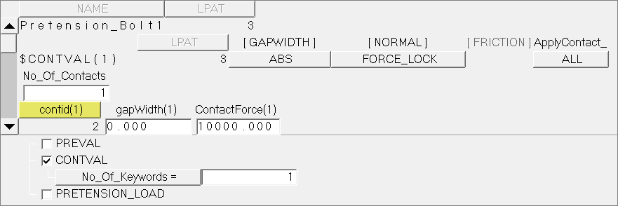
| 16. | Click return to close the card image. |
| 17. | In the Model browser, right-click and select Create > Load Collector from the context menu. |
| 18. | In the Create Load Collector dialog: |
| • | For Name, enter Pretension_Bolt2. |
| • | Select a color for the load collector. |
| • | Set Same as to Pretension_Bolt1. |
| 19. | In the card image, double-click contid(1) and select Bolt_2. |
| 20. | Click return to close the card image. |
| 21. | In the Model browser, right-click and select Create > Load Collector from the context menu. |
| 22. | In the Create Load Collector dialog: |
| • | For Name, enter Gap_Tube_Clamps. |
| • | Select a color for the load collector. |
| • | Set Card image to LOADS. |
| • | Select the Card edit loadcollector upon creation checkbox. |
| 23. | In the card image, select the CONTVAL checkbox. |
| 24. | Under No_of_Contacts, enter 2. |
| 25. | Double-click contid(1), and select Gap. |
| 26. | Double-click contid(2), and select tube_clamps. |
| 27. | Click GAPWIDTH, and select ABS. |
| 28. | Click NORMAL, and select CALCULATE. |
| 29. | Click return to close the card image. |
Step 15: Define the $NLLOAD cards
In this step you will create a $NLLOAD card to specify how individual load patterns are acting over an artificial time.
| 1. | Open the Load Steps panel by clicking Setup > Create > Load Steps from the menu bar. |
| 2. | In the name field, enter NLLOAD. |
| 3. | Using the loadcols selector, select the following load collectors: Single_Load, Pretension_Bolt1, Pretension_Bolt2, and Gap_Tube_Clamps. |
| 5. | Click edit to open the card image. |
| 6. | Select the NLLOAD checkbox. |
| 7. | In the TimeSteps field, enter 4. |
| 8. | In the NoOfLPATS field, enter 4. |
| 9. | Using the LPAT selectors, select load collectors as follows: |
| • | LPAT(1) - Gap_Tube_Clamps |
| • | LPAT(2) - Pretension_Bolt1 |
| • | LPAT(3) - Pretension_Bolt2 |
| 10. | Enter the following information for each of the load patterns as shown in the image below: |
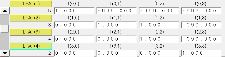
| 11. | Click return twice to close the panels. |
The NLLOAD card has been defined. Use the Plot NNLOAD tool, located on the Utility menu, to review the contents of the card. You can see the load history of each load pattern plotted as a graph. You also can edit values within the table of the tool. See the topic Creating an NLLOAD Card in the HyperMesh online help for more information.
| Note: | The entry fields for the NLLOAD entries require real numbers, and cannot understand hyphens, which are used commonly by PERMAS users. However, to define a hyphen for export you can write -999 which will display as ‘-‘ in the exported deck. This applies to imported files, too. A hyphen will convert to ‘-999’ on import. |
|
Step 16: Define the $SITUATION card
In this step, you will build a $SITUATION card which specifies which loads, boundary conditions, and system definitions are combined for this analysis.
| 1. | Open the Load Steps panel. |
| 2. | In the name field, enter SIT_NLLOAD. |
| 4. | Click edit to open the card image. |
| 5. | Set AnalysisProcedure to SITUATION. |
| 6. | Using the CONSTRAINTS selector, select Con_1. |
| 7. | Using the LOADING selector, select NLLOAD. |
| 8. | Click return twice to close the card image and then the panel. |
Step 17: Export the deck to a .dat file
| 1. | From the menu bar, click File > Export > Solver Deck. The Export - Solver Deck tab opens. |
| 2. | In the File field, enter tube_clamp_final.dat. |
| 3. | Next to Export Options, click  . . |
Acknowledgements
Altair thanks INTES for their assistance and support during the creation of this tutorial.
See Also:
HyperMesh Tutorials


