Normal Modes Process |

|

|

|

|
|
Normal Modes Process |

|

|

|

|
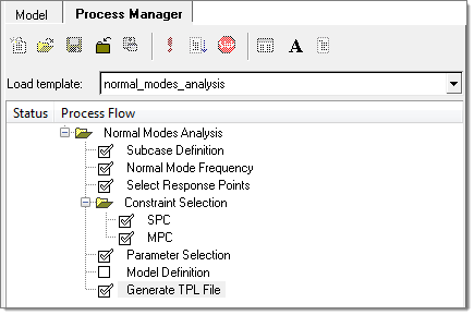
When the Normal Modes Process is started, the Process Manager tool is invoked. A normal modes analysis process template is loaded into the Process Flow browser, which includes process steps, each with one or more sub tasks. For each task, a data input dialog is presented in the panel area.
The Normal Modes loadcase Process Manager automatically generates a loadcase template, which can be used in the Analysis Manager for future normal modes loadcases without going through the Process Manager again.

The subcase definition task allows you to create a new subcase or edit an existing subcase. To create a new subcase, edit the optional subcase label and click Add. To edit an existing subcase, highlight an existing subcase in the list box, edit the optional subcase label and click Update. Once input to the task is complete, click Apply to proceed to the next task.
|
This task allows you to input normal modes extraction parameters, such as Min. and Max. frequency, or the number of modes desired. In most cases, only input for the Max. frequency field is needed. When left blank, the Min. frequency is interpreted as 0 (Hz.), and the No. of modes is however many found between 0 and the Max. frequency. This task gives you separate control over modal extraction in the structural and fluid domains. Once input to the task is complete, click Apply to proceed to the next task.
|
This task lets you pick responses for output. First select a response type, such as Displacement, then pick nodes, a node set, or tags to be included in a particular response set. You can add or delete multiple response sets from the list using the Add row and Delete row icons to the right of the list. You can also specify the complex frequency response data format (real/imaginary or magnitude/phase) and the output file format (h3d, punch, or op2). Once all the required responses have been defined, click Apply to proceed to the next task.
|
This task lets you define the boundary condition of the frequency response analysis. You can select existing SPCs by checking the corresponding box under the Active column, or click Create SPC to go to the Constraints panel and define a new SPC. Once the boundary condition has been fully defined, click Apply to proceed to the next task.
|
This task lets you select MPC equations to turn on for the frequency response analysis. When you are in the NVH user profile, there are two options for managing MPCs, the Analysis Manager and the Process Manager. If you select the Analysis Manager the Select subcase option and the MPCs list are disabled. If you select the Process Manager, after you select a subcase you can then select existing MPCs by checking the corresponding box under the Active column. Once the MPC equations have been selected, click Apply to proceed to the next task. When you are in the HyperMesh user profile the Analysis Manager option is not available, and the MPCs can only be managed through the Process Manager. |
This task lets you select typical solution parameters, such as title, singular point constraints, and so on. Check all boxes under the Active column to activate the desired solution option. Once the parameters have been selected, click Apply and a Process Manager message box pops up informing you that the process has come to an end. Click Yes to close the template, or No to review or edit the process steps.
|
This task allows you to generate and save the parameters defined in a standard template file at your selected location. In the Analysis Manager, the generated template file can be selected as loadcase and solver decks can be exported for normal modes analysis.
|