In this tutorial, you will learn how to:
| • | Define a model in HyperMesh |
| • | Apply boundary conditions in HyperMesh |
| • | Write the Nastran input deck |
You will use the HyperMesh Nastran interface to create finite elements on the geometry of a plate with a hole, apply boundary conditions, and perform finite element analysis.
Model Files
This tutorial uses the plate_hole.hm file, which can be found in <hm.zip>/interfaces/nastran/. Copy the file(s) from this directory to your working directory.
Exercise
Step 1: Retrieve the model file and select the Nastran user profile
| 1. | Start HyperMesh Desktop. |
| 2. | In the User Profile dialog, set the user profile to Nastran. |
| 3. | Open a model file by clicking File > Open > Model from the menu bar, or clicking  on the Standard toolbar. on the Standard toolbar. |
| 4. | In the Open Model dialog, open the plate_hole.hm file. |
Step 2: Create material collectors and components
| 1. | In the Model browser, right-click and select Create > Material from the context menu. A new material opens in the Entity Editor. |
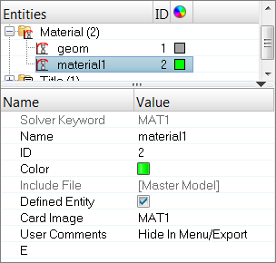
| 3. | Set Card Image to MAT1. |
| 6. | For RHO, enter any number (if needed). |
| 7. | In the Model browser, right-click and select Create > Component from the context menu. A new component opens in the Entity Editor. |
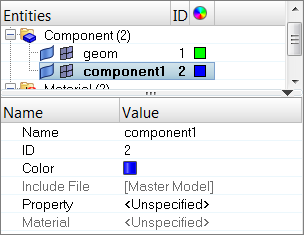
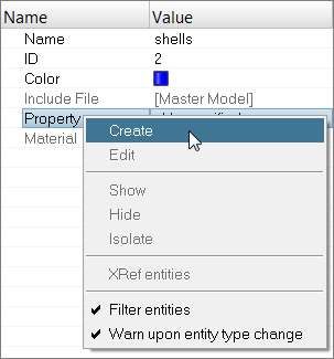
| 8. | For Name, enter shells. |
| 9. | Right-click on Property and select Create from the context menu. |
| 10. | In the Create Properties dialog, Name field, enter pshells. |
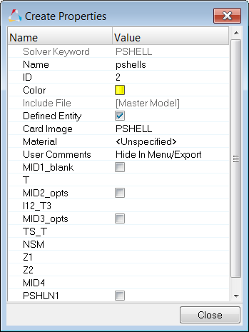
| 11. | Set Card Image to PSHELL. |
| 12. | For T (thickness), enter 1.0. |
| 13. | Click Close. HyperMesh assigns the property pshells to the component shells. |
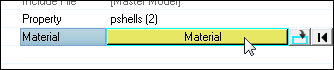
| 14. | For Material, click Unspecified >> Material. |
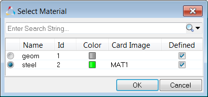
| 15. | In the Select Material dialog, select steel and then click OK. HyperMesh assigns the material steel to the component shells. |
Step 3: Mesh the geometry
Use the Automeshing panel to mesh interactively on surfaces. This panel contains tools for manipulating surface edges and meshing fixed points (locations where the mesher is required to place a node.) The elements generated are organized into the current component and shells.
| 1. | Open the Automesh panel by pressing F12. |
| 2. | Go to the size and bias subpanel. |
| 3. | Click surfs >> displayed. |
| 4. | In the element size field, enter 40. |
| 5. | Set the elems to surf comp/elems to current comp toggle to elems to current comp. |
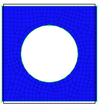
| 6. | Click mesh. HyperMesh meshes the selected surfaces, and the meshing module opens. |
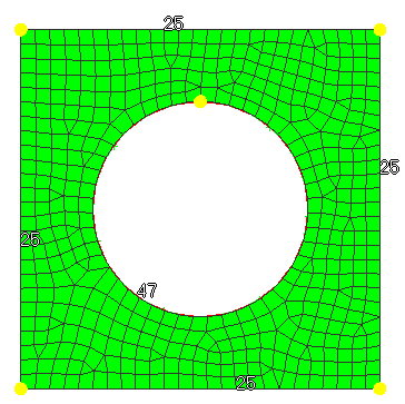
Plate mesh using element size of 40mm
| 7. | Accept the mesh in the shells component by clicking return. |
| 8. | Close the Automesh panel by clicking return. |
Steps 4-6: Apply boundary conditions to the model
In this section, the model is constrained so that two of the four edges cannot move. A total lateral load of 1000N is applied at the edge of the hole so that all forces point in the positive z-direction.
Step 4: Create collectors
Before creating boundary condition and loads, load collectors are created first. These load collectors are used for boundary conditions and loads.
| 1. | In the Model browser, right-click and select Create > Load Collector from the context menu. A new load collector opens in the Entity Editor. |
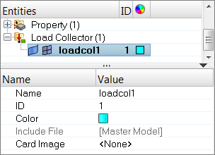
| 3. | Click the Color icon and select a color to display the load collector. |
| 4. | Create a second load collector labeled, forces. |
Step 5: Create constraints
| 1. | In the Model browser, Load Collector folder, right-click on spcs and select Make Current from the context menu. |
| 2. | Open the Constraints panel by clicking BCs > Create > Constraints from the menu bar. |
| 3. | Go to the create subpanel. |
| 4. | Set the entity selector to nodes. |
| 5. | Click nodes >> by window. |
| 6. | Select the exterior checkbox. |
| 7. | With the exception of the nodes at the ends, draw a box around all of the displayed nodes. |
| 8. | Click select entities. HyperMesh selects all of the nodes outside of the window you drew. |
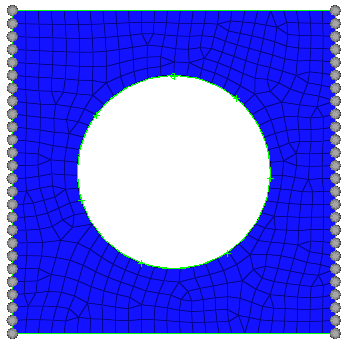
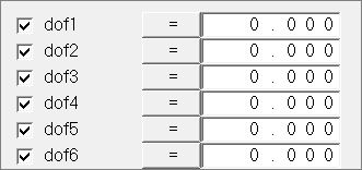
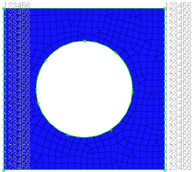
| 9. | Select all of the dof (degree of freedom) checkboxes. |
| Note: | Dofs that are checked are constrained. Dofs 1, 2, and 3 are x, y, and z translation degrees of freedom, and dofs 4, 5, and 6 are x, y, and z rotational degrees of freedom. |
| 10. | Apply these constraints to the selected nodes by clicking create. |
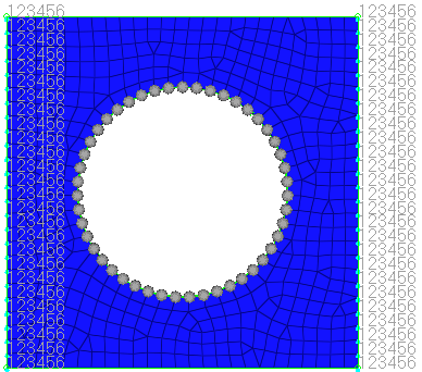
Step 6: Create forces on the nodes around the hole
| 1. | In the Model browser, Load Collector folder, right-click on forces and select Make Current from the context menu. |
| 2. | Open the Forces panel by clicking BCs > Create > Forces from the menu bar. |
| 3. | Click nodes >> by path. |
| 4. | Select all of the nodes around the hole of the model. |
| 7. | Open the Count panel by going to the Tool page and clicking count. |
| 8. | Go to the FE entities subpanel. |
| Note: | Nodes are automatically counted so that a calculation can be made to create a total force of 1000N. |
| 9. | Set the entity selector to nodes. |
| 10. | Retrieve the nodes you saved in the Forces panel by clicking nodes >> retrieve. |
| 11. | Click selected. HyperMesh counts the number of nodes around the hole. |
| 13. | Open the Forces panel. |
| 14. | Click nodes >> retrieve. |
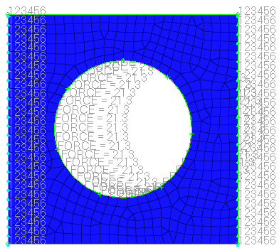
| 15. | In the magnitude = field, enter 21.277 (this is 1000/47). |
| Note: | The total load on the nodes around the hole is 1000N. |
| 16. | Set the orientation selector to z-axis. |
Steps 7-8: Create a Nastran subcase (a load step in HyperMesh)
Step 7: Create the loadstep
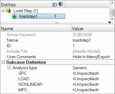
| 1. | In the Model browser, right-click and select Create > Loadstep from the context menu. A new loadstep opens in the Entity Editor. |
| 2. | For Name, enter lateral force. |
| 3. | For SPC, click Unspecified >> Loadcol. |
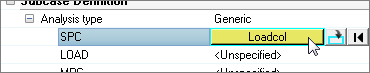
| 4. | In the Select Loadcol dialog, select spcs and then click OK. |
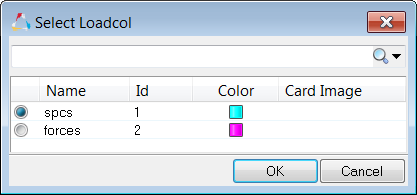
| 5. | For LOAD, click Unspecified >> Loadcol. |
| 6. | In the Select Loadcol dialog, select forces and then click OK. |
| 7. | Under SUBCASE OPTIONS, select the OUTPUT checkbox. |
| 8. | Under OUTPUT, select the DISPLACEMENT checkbox. |
| 9. | Under OUTPUT, select the STRESS checkbox. |
Step 8: Create control cards
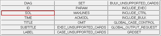
| 1. | From the menu bar, click Setup > Create > Control Cards. |
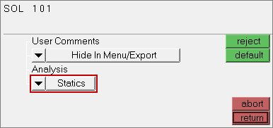
| 2. | In the Card Image panel, click SOL. |
| 3. | Set Analysis to Statics. |
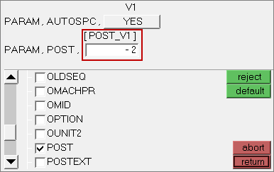
| 6. | Select the AUTOSPC and POST checkboxes. |
| 7. | In the card edit field, click POST_V1 and enter -2 in the editable field. |
| Note: | This option specifies that an op2 file should be created. |
Steps 9-10: Write the Nastran input deck
In this section, write the Nastran input deck file, specified with the .dat extension, before running Nastran.
Step 9: Write your file
| 1. | From the menu bar, click File > Export > Solver Deck. The Export - Solver Deck tab opens. |
| 2. | Set File type to Nastran. |
| 3. | In the File field, navigate to your working directory an save the file as plate_hole.dat. |
| 4. | Click Export. HyperMesh writes your HyperMesh database as a Nastran ASCII input deck. |
Step 10: Save your file and exit HyperMesh
| 1. | From the menu bar, click File > Save As > Model. |
| 2. | In the Save Model As dialog, navigate to your working directory and save the file as plate_hole_new.hm. |
Steps 11-14: View the results
After running Nastran, the punch file plate_hole.op2 is created. This file contains displacement and stress results for your linear static analysis. This section describes how to view those results in HyperMesh.
Step 11: Add a HyperView page to the session and load the fem and op2 files
| 1. | On the Page Controls toolbar, click  . . |
| 2. | Set the Client Selector toolbar to HyperView. |
| 3. | From the menu bar, click File > Open > Model. The Load Model panel opens. |
| 4. | In the Load model field, navigate to your working directory and open the plate_hold.dat file. |
| 5. | In the Load results field, navigate to your working directory and open the plate_hold.op2 file. |
| 6. | Click Apply. HyperView loads the model and results. |
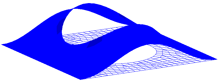
Step 12: View a deformed shape
| 1. | Open the Deformed panel by clicking Results > Plot > Deformed from the menu bar. |
| 2. | Set Result type to Displacement. |
| 3. | Set Scale to Model units. |
| 6. | Under Undeformed shape, set Show to Wireframe. |
| 7. | View a deformed plot of your model overlaid on the original, undeformed mesh by clicking Apply. |
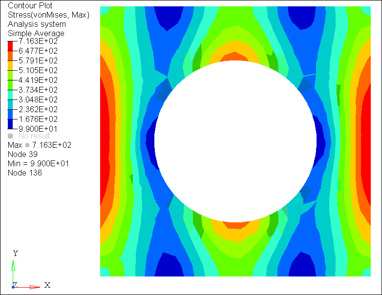
Step 13: View a contour plot of stresses and displacements
| 1. | Open the Contour panel by clicking Results > Plot > Contour from the menu bar. |
| 2. | Set Result type to Displacement (v). |
| 3. | On the Standard Views toolbar, click  . . |
| 5. | Set Result type to Stress (t). |
| 6. | Set Averaging method to Simple. |
See Also:
HyperMesh Tutorials


