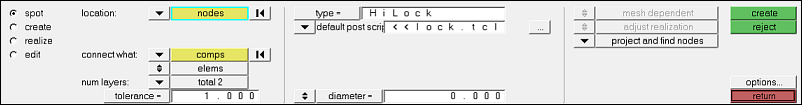
The HiLock realization type is available for Nastran and OptiStruct.
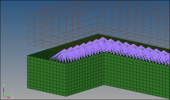
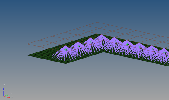
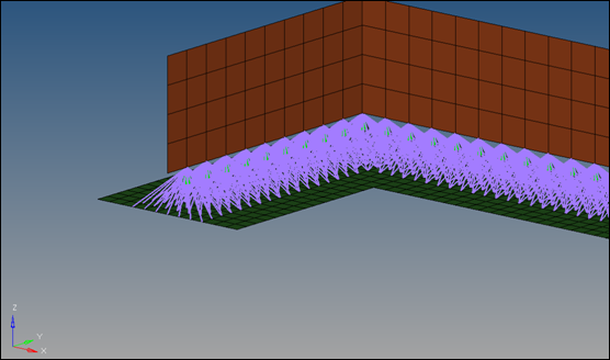
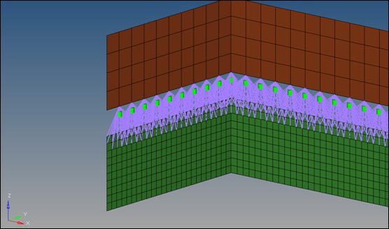
It can be used for any more or less parallel combination of PSHELL and PCOMP elements, and creates a 1D element construct consisting of RBAR, CBAR and CBUSH elements.
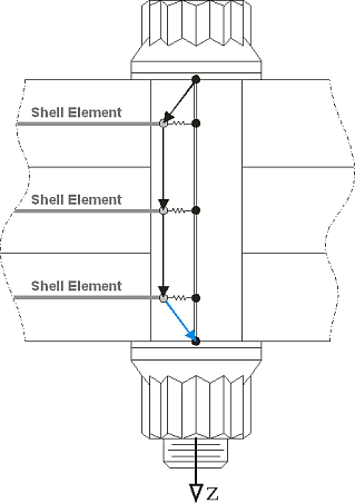
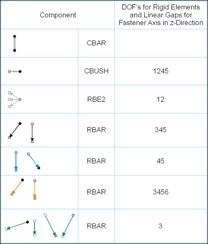
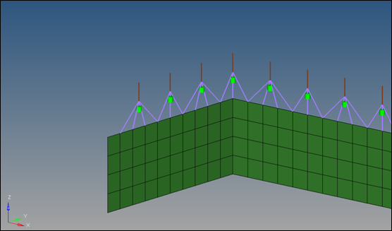
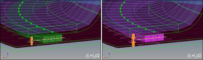
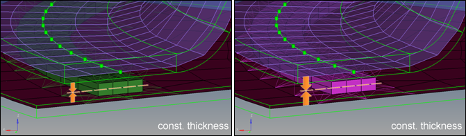
The outer extensions represent the thicknesses of the outer shell elements. The inner nodes of the RBAR element are connected to the shell elements whereas the inner nodes of the CBAR elements are coincident to the shell nodes. Between the appropriate connected and coincident nodes CBUSH elements are created. Each outer node connects one CBAR and one RBAR.
Each HiLock connection gets its own coordinate system with the z-axis collinear to the HiLock direction. All affected nodes are assigned to this coordinate system, which is taken into account for the DOF definition of the CBAR elements, the stiffness calculation of the CBUSH elements, and the DOF of the node constraint.
This realization uses the shell properties and materials (PSHELL or PCOMP) and a definable HiLock material to calculate the exact position of the outer nodes and the stiffness of the PBUSH elements.
Certain conditions must be met for reliable realization:
| • | In the case of composites, only PCOMP cards in which the laminate option is either blank or set to SYM (symmetric) are supported. MEM, BEND, SMEAR, and SMCORE options are not supported for HiLock realization, and will cause realization to fail if used. |
| • | The joined shells should be parallel to each other and planar. |
| • | The fastener should be perpendicular to the shells. |
| • | The z-axis of the element system, the material system, and the fastener system should be collinear. |
| • | Stiffness is calculated assuming that the shells are perfectly planar and parallel. Small deviations will produce insignificant changes in predicted stiffness, but larger ones would require a system transformation. |
| • | The shell elements which share a node with the HiLock (separate for each layer) should have the same properties, same materials, same material orientations, and similar sizes. The attributes of the element upon which the projection falls is assumed to be the same as the other surrounding elements (no averaging method is used.) |
If attributes necessary for the stiffness calculation are missing, the connector fails and an error message displays in the status bar.
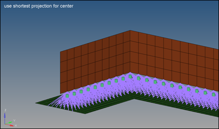
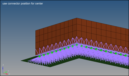
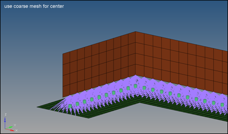
The realization requires available nodes near the connector position. If sufficient nodes are not available, the created elements are not collinear anymore and the HiLock gets a questionable geometry.
|
All HiLock elements (RBARs, CBARs, CBUSHs) created during the realization process are organized into a component named HiLock.
The following property collectors are created:
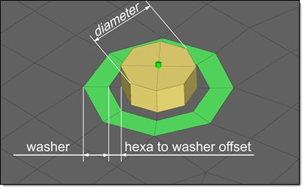
| • | HiLock_PBAR_<diameter>: This property collector is created with the PBAR card associated with it. The RBAR elements reference this property. The attributes are calculated depending on the diameter specified in the Spot panel during realization. |
| • | HiLock_PBUSH_<translational stiffness>_<rotational stiffness>: These property collectors are created with the PBUSH card associated with them. The CBUSH elements reference this property. The attributes are calculated depending on the chosen HiLock material and the properties and materials of the connected shells (PSHELL and/or PCOMP). |
The following load collector is created:
| • | HiLock_SPC6: the SPCs which are created for each HiLock are moved into it. |
The following system collector is created:
| • | HiLock: Systems created during the realizations will be moved into this collector. If this system collector already exists, any newly created systems will be moved into the same collector. |
If a HiLock material is not selected, a default material is created:
| • | HiLock_MAT1: This material will be assigned to the PBAR cards, and can be found in the following folder of the installation directory: [hm_scripts_dir]/connectors/HiLock_Mats. |
The predefined values are:
set E 1.8+07
set G 4.7e+04
set NU 0.330
set RHO 8.9e-09set A 1.7e-05
|
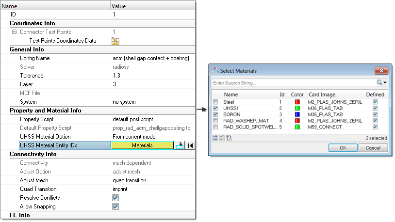
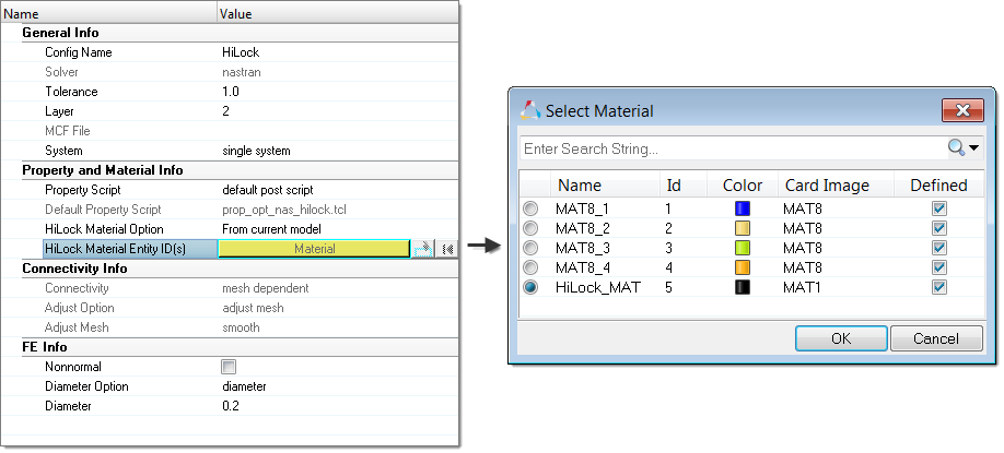
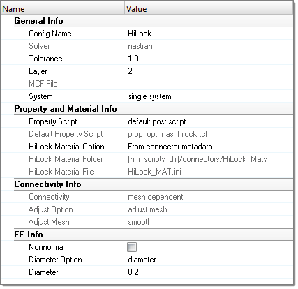
When defining a HiLock connector, the HiLock Material Option can be selected for individual connectors using the Connector Entity Editor.
| • | From current model. Select an existing material from the current model. |
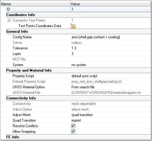
| • | From search folder (default). For HiLock realizations the material search folder is HiLock_Mats. HyperMesh searches for this folder in the following locations and in the following order: |
| 1. | Installation: [hm_scripts_dir]/connectors/Hilock_Mats |
| 2. | User directory: [USER_HOME]/HiLock_Mats |
| 3. | HyperWorks Configuration Path folder: [HW_CONFIG_PATH]/Hilock_Mats |
| 4. | Current working folder: [CURRENTWORKINGDIR]/HiLock_Mats |
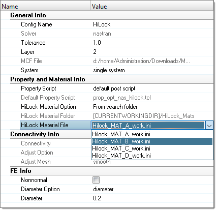
In the Connector Entity Editor, the HiLock Material Folder field is populated with the name of the folder that was found last. Only the files in this HiLock_Mats folder are considered and can be selected in the HiLock Material File field.
By default, the first file listed (alphabetical order) in the folder is automatically populated in the HiLock Material File field, and will be used when realizing a connector from the panel. For this reason, it is important that you only keep valid material files in the HiLock_Mats folders.
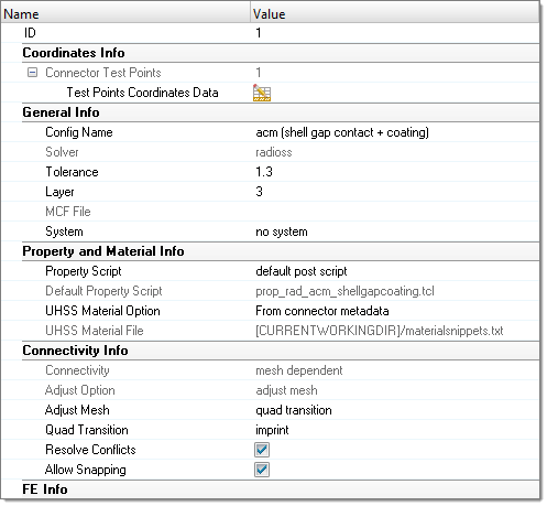
| • | From connector metadata: Once a connector is realized with the HiLock Material Option “From Search Folder”, the folder and file name is written as metadata to the connector. Folder data is saved in a relative manner to allow the exact same rerealization in a different work environment as long as the materials are saved in according folders. |
If the materials are not available as the metadata states, the realization will fail and the following message with be displayed: Material file/id not found.
|
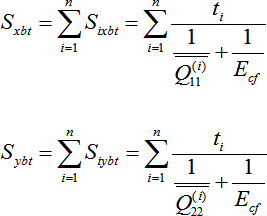
Combined translational bearing stiffness at composite plate with the fastener contact
(these values are defined for every composite plate in the joint).
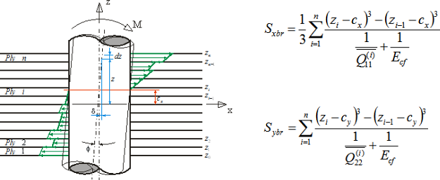
After summation of bearing stiffness of plies where n = number of plies in the composite plate:
Combined translational bearing stiffness of the joint at ply i location in directions x and y.
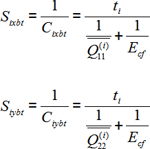
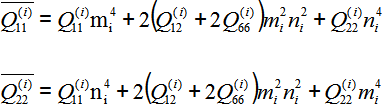
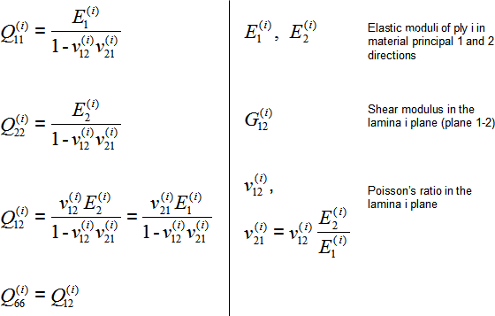
Transformed reduced stiffness in x and y-direction for ply i.
 Where Where

(theta = angle of orientation for ply i)
And
nonzero components of the reduced stiffness matrix for ply i are:
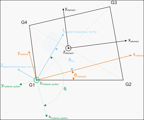
Angle of ply i orientation in a CQUAD4 element.
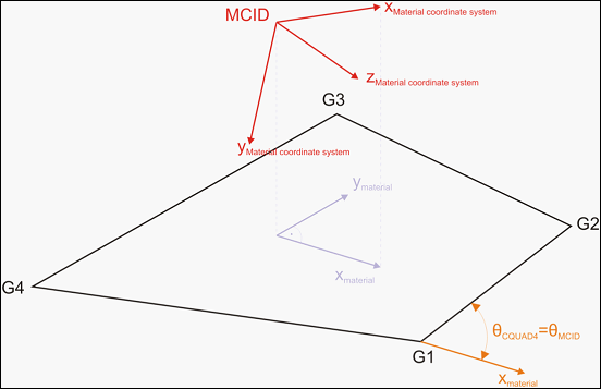
Material orientation of a CQUAD4 defined by a coordinate system.
Rotational bearing stiffness in plate-fastener contact.
|
Combined translational bearing stiffness at metallic plate with the fastener contact
After summation of bearing stiffness of plies where n = number of plies in the composite plate:

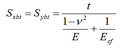
Where
t = thickness of metallic part
E = elastic compression modulus of metallic (isotropic) part
v = Poisson's ratio
Rotational bearing stiffness at metallic plate with the fastener contact

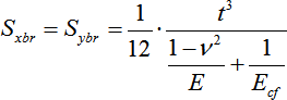
Where
t = thickness of metallic part
E = elastic compression modulus of metallic (isotropic) part
v = Poisson's ratio
|
|