For this tutorial it is recommended that you complete the introductory tutorial, HM-1000: Getting Started with HyperMesh.
This tutorial introduces the HyperMesh interface to PAM-CRASH 2G. The following exercises are included:
| • | Load a prepared HyperMesh file |
| • | Select the Pam-Crash 2G user profile |
| • | Define HyperMesh groups: sliding interface |
| • | Creating boundary conditions |
| • | Exporting a Pam-Crash 2G data deck from HyperMesh |
Model Files
This tutorial uses the rail-dyna.hm file, which can be found in <hm.zip>/interfaces/pamcrash/. Copy the file(s) from this directory to your working directory.
Exercise
Step 1: Select the PAM-CRASH 2G user profile
In order to use HyperMesh with a specific solver, the solver user profile must be loaded. Upon opening, you are prompted to select a user profile. In the User Profiles dialog, select the PAM-CRASH 2G profile.
Selecting the PAM-CRASH 2G user profile sets the FE input reader to PAM-CRASH 2G and loads the PAM-CRASH 2G 2006 FE output template. It also loads the PAM-CRASH 2G Utility menu, which contains numerous tools specific to this interface. The graphical user interface is tailored to PAM-CRASH 2G users.
Step 2: Load a prepared HyperMesh file
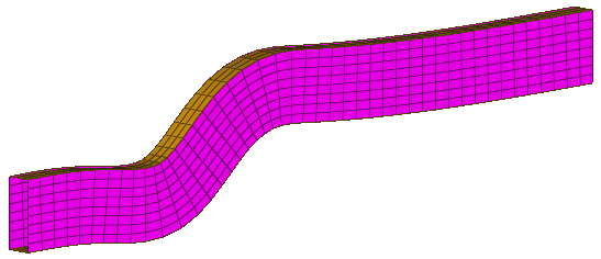
A prepared model with elements and nodes is included in the <install_directory>\tutorials\hm\interfaces\pamcrash directory. The file name of the example is rail-dyna.hm. This is the basic example on which the tutorial is based.
| 1. | Open a model file by clicking File > Open > Model from the menu bar, or clicking  on the Standard toolbar. on the Standard toolbar. |
| 2. | In the Open Model dialog, open the rail-dyna.hm file. |
Steps 3-6: Create Control Cards for PAM-CRASH 2G
This section explains how to create control cards for the CONTROL SECTION of the PAM-CRASH 2G deck.
| Note: | The settings of the control cards influence the default values for defining materials. No PAM-CRASH 2G deck can be executed without error if control cards are undefined. |
|
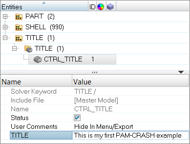
Step 3: Define the title card
| 1. | In the Solver browser, right-click and select Create > CONTROL CARDS > TITLE from the context menu. A new control card opens in the Entity Editor. |
| 2. | In the TITLE field, enter This is my first PAM-CRASH example. |
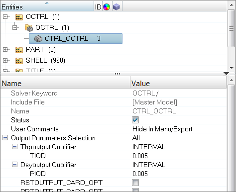
Step 4: Define the output control cards
| 1. | In the Solver browser, right-click and select Create > CONTROL CARDS > OCTRL from the context menu. A new control card opens in the Entity Editor. |
| Note: | The OCTRL control card defines output control parameters. |
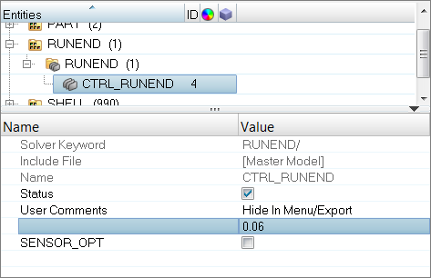
| 4. | In the Solver browser, right-click and select Create > CONTROL CARDS > RUNEND from the context menu. A new control card opens in the Entity Editor. |
| Note: | The RUNEND control card defines end of run parameters. |
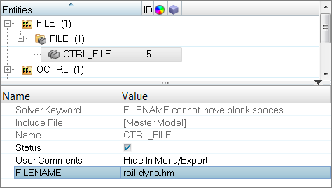
Step 5: Define the file optional keyword
| 1. | In the Solver browser, right-click and select Create > CONTROL CARDS > FILE from the context menu. A new control card opens in the Entity Editor. |
| 2. | For FILENAME, enter rail-dyna.hm. |
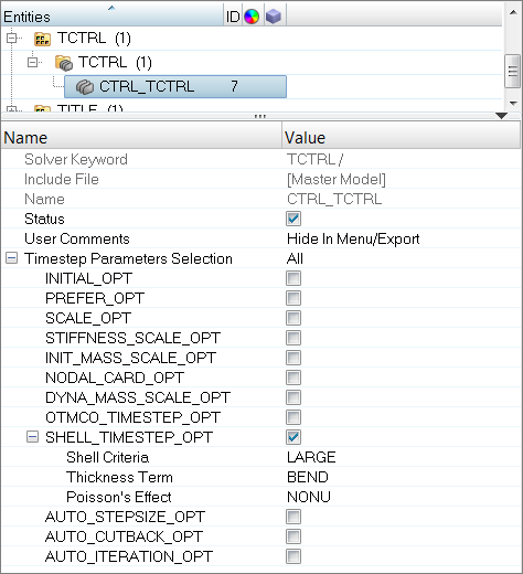
Step 6: Define the time step optional keyword
| 1. | In the Solver browser, right-click and select Create > CONTROL CARDS > TCTRL from the context menu. A new control card opens in the Entity Editor. |
| 2. | Select the SHELL_TIMESTEP_OPT checkbox. |
| 3. | Set Shell Criteria to LARGE (default). |
| 4. | Set Thickness Term to BEND (default). |
Step 7: Assign Element Types for PAM-CRASH 2G
Depending on the analysis requirement, the HyperMesh basic element type can be changed.
For example, a quad4 can be a SHELL or a MEMBR element. The tria3 element can be a TRIA_C, SHELL, or MEMBR element. The tetra4, the penta6, and the hexa8 elements define the SOLID elements of PAM-CRASH. Properties can be added for the selected element type using control cards.
| 1. | Open the Element Type panel by clicking Mesh > Assign > Element Type from the menu bar. |
| 2. | Go to the 2D & 3D subpanel. |
| 3. | Click quad4 = and select SHELL. |
| 6. | Click return to exit the panel. |
Steps 8-10: Define material and /PART cards for PAM-CRASH 2G
Before proceeding with the tutorial you will rename the component tmp.
| 1. | In the Model browser, Component folder, click tmp component. The Entity Editor opens, and displays the component's card data. |
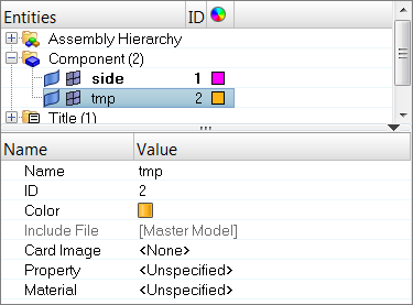
| 2. | For Name, enter topbottom. |
Step 9: Define a Material Type 102
| 1. | In the Model browser, right-click and select Create > Material from the context menu. A new material opens in the Entity Editor. |
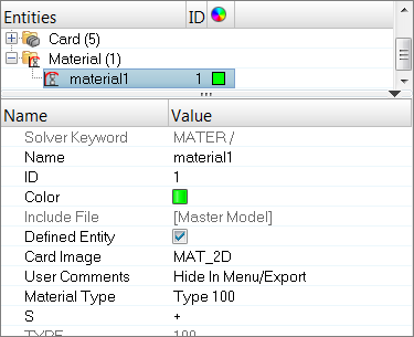
| 2. | For Name, enter new mat. |
| 3. | Set Card Image to MAT_2D. |
| Note: | The template provides MAT_1D, MAT_2D, and MAT_3D dictionaries. Material types from 200 to 230 are defined with MAT_1D. Materials types from 100 to 151 are defined with MAT_2D. Material types from 1 to 41 are defined with MAT_3D. To switch the material type, use the card previewer. |
| 4. | Set Material Type to Type 102. |
| 5. | For density, enter 7.85e-9. |
Step 10: Assign material and thickness to side and topbottom collectors
| 1. | In the Model browser, Component folder, select side and topbottom. The Entity Editor opens and displays the selected component's common card data. |
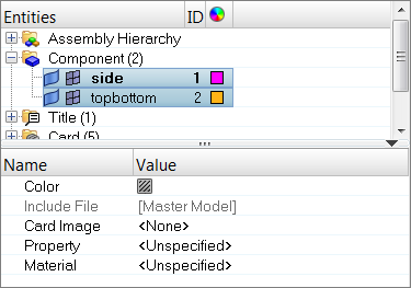
| 2. | Set Card Image to Part_2D. |
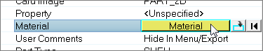
| 3. | For Material, click Unspecified >>Material. |
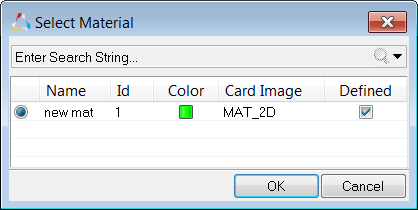
| 4. | In the Select Material dialog, select new mat and then click OK. HyperMesh assigns the new mat material to the selected components. |
| 5. | For h (thickness), enter 2.5. |
Steps 11-14: Define HyperMesh Groups: Sliding Interface for PAM-CRASH 2G
This section describes how to define a self contacting sliding interface. A second interface is defined only for tutorial purposes.
The procedure below explains how to define a type 36 self contacting sliding interface.
Step 11: Define the group
| 1. | In the Solver browser, right-click and select Create > CNTAC > CNTAC36 from the context menu. A new group opens in the Entity Editor. |
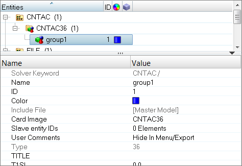
| 2. | For Name, enter self_impact. |
| 3. | Select a new color for the group. |
| 5. | For TITLE, enter This is the selfimpact interface. |
Step 12: Add the slave components
In this step, the Entity Editor should still be open for the self_impact group.
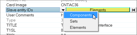
| 1. | Click Slave entity IDs. |
| 2. | Set the entity selector to Components. |
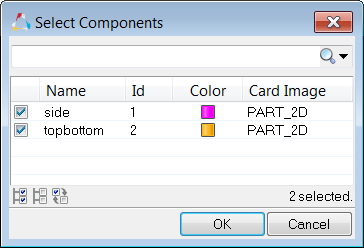
| 4. | In the Select Components dialog, select side and topbottom and then click OK. |
Step 13: Define an additional contact
This procedure explains how to define a type 34 master slave (element - node) contact.
| 1. | In the Solver browser, right-click and select Create > CNTAC > CNTAC34 from the context menu. A new group opens in the Entity Editor. |
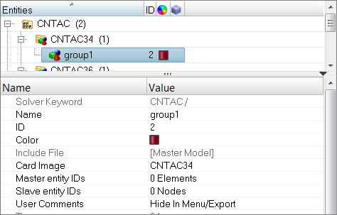
| 2. | For Name, enter masterslave. |
| 3. | Select a new color for the group. |
Step 14: Add the master elements and slave nodes
In this step, the Entity Editor should still be open for the masterslave group.
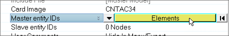
| 1. | For Master entity IDs, click 0 Elements >> Elements. |
| 2. | In the panel area, set the switch to elems. |
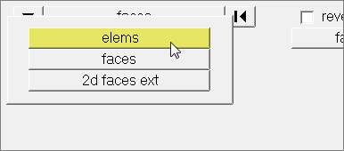
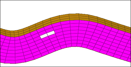
| 3. | Using the elems selector, select two elements. |
| 6. | For Slave entity IDs, click 0 Nodes > Nodes. |
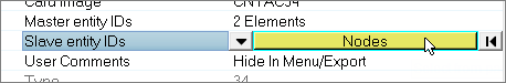
| 7. | In the panel area, set the switch to nodes. |
| 8. | Using the nodes selector, select two nodes. |
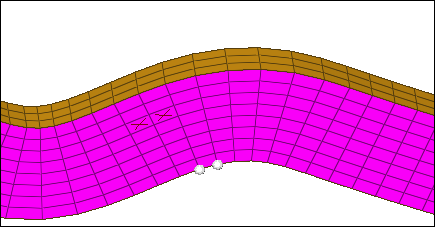
| 10. | Click return. The master elements are marked with and X, and the slave nodes displays. |
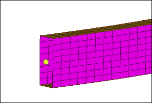
Steps 15-19: Define a Rigid Wall for PAM-CRASH 2G
This section explains how to define a type 4 infinite rigid wall with a base node at -1.00, 0.0, 0.0.
Step 15: Create a base node for the rigid wall
| 1. | From the menu bar, click Geometry > Create > Nodes > XYZ. |
| 6. | Click return to exit the panel. |
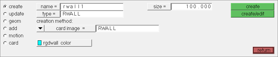
Step 16: Create and define the rigid wall card
| 1. | From the menu bar, click BCs > Create > Rigid Walls. |
| 2. | In the Rigid Walls panel, Name field, enter rwall1. |
| 3. | Click type = and select RWALL. |
| 4. | Click rgdwall color and select a color. |
| 5. | In the size =, enter 100. |
| Note: | This specifies the display size of the rigid wall. |
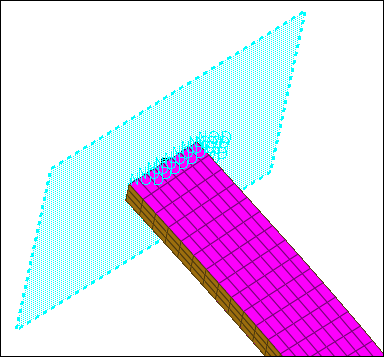
Step 17: Define rigid wall geometry
| 1. | Go to the geom subpanel. |
| 2. | Double-click name=, and select rwall1. |
| 3. | Set the switch after shape to plane. |
| 4. | Set the toggle after shape to infinite. |
| 5. | Under normal vector, set the switch to vectors. |
| 6. | Click the second switch and select x-axis. |
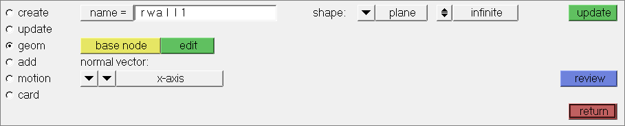
| 7. | Using the base node selector, select the node you created in step 15. |
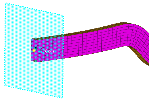
| 8. | Click update. The rigid wall displays. |
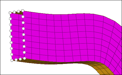
Step 18: Add slave nodes for the rigid wall
| 1. | Go to the add subpanel. |
| 4. | In the id field, enter 1-21 and then press ENTER. |
| Note: | 21 nodes at the interface of the rail and the rigid wall highlight. One of the nodes was not selected. |
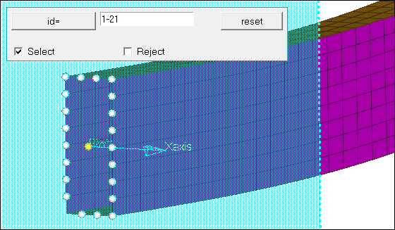
| 5. | Click the node that was not highlighted. |
Or
Click nodes >> id, and enter 1012 in the id field.
| 6. | Click add. The selected nodes are now set as slaves. |
Step 19: Add motion to the rigid wall
| 1. | Go to the motion subpanel. |
| 2. | Set the switch below name to components. |
| 3. | In the x comp field, enter 1.0. |
| 4. | Set type of motion to velocity. |
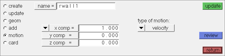
| 6. | Click return to exit the panel. |
Step 20: Define attributes in the card previewer
| 1. | In the Model browser, Group folder, click rwall1. The Entity Editor opens and displays the group's card data. |
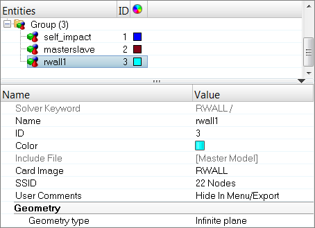
| 2. | Set Friction type flag to No Sliding. |
| 3. | Set Rigid Wall Descriptor – Plane Type to Type 4. |
| Note: | The parameters in the Entity Editor according to the definitions made. It is now possible to define the mass and the initial velocity for moving rigid wall with finite mass. |
Steps 21-22: Create boundary conditions for PAM-CRASH 2G
This section explains how to create model boundary conditions.
Step 21: Create a load collector
| 1. | In the Model browser, right-click and select Create > Load Collector from the context menu. A new load collector opens in the Entity Editor. |
| Note: | The new load collector becomes the current collector. Any new loads created will be placed in this collector. |
| 2. | For Name, enter boundary conditions. |
| 4. | Click the Color box, and select a color. |
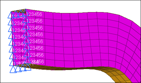
Step 22: Specify the constraints
| 1. | Open the Constraints panel by clicking BCs > Create > Constraints from the menu bar. |
| 2. | Click load types, and select BOUNC. |
| Note: | All constraints that are now created will be displacement boundary conditions. |
| 4. | In the id field, enter 990-1011. |
| 5. | Press ENTER. 22 nodes highlight. |
| 6. | In the size field, enter 10. |
| 7. | Click create. Constraints are now added to the selected nodes. |
| 8. | Click return to exit the panel. |
Steps 23-26: Create Time Histories for PAM-CRASH 2G
For PAM-CRASH 2G, time histories may be defined for nodes, elements, and local coordinate systems. For this exercise, you will only create time histories for some nodes and elements. The operation is the same for any type of time history that is created.
Step 23: Create a node time history card
| 1. | In the Model browser, Load Collector folder, right-click on Boundary Conditions and select Hide from the context menu. The display of loads turns off. |
| 2. | From the menu bar, click Setup > Create > Output Blocks. |
| 3. | In the name field, enter node_thp. |
| 4. | Using the nodes select, select a few nodes. |
| 5. | Click create. The time history for nodes is created. |
Step 24: Create an element time history card
| 1. | In the name field, enter elem_thp. |
| 2. | Set the entity selector to elems. |
Step 25: Review time histories entities
| 2. | Select elem_thp. The entities associated with this time history highlight. |
| 3. | Click return to exit the panel. |
Step 26: View the time history card image
| 1. | In the Model browser, Right click on the elem_thp output block in the Model Browser and click Card Edit. |
The time history card is displayed as it will look in the output.
| 2. | Click return twice to exit the panel. |
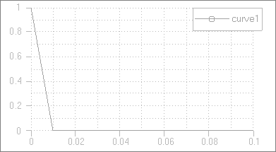
Step 27: Create a function
This section describes how to generate curves, which corresponds to the function cards /FUNCT in PAM-CRASH2G. This curve should serve as a function for a logical sensor switching on and off. At time=0, the sensor is on, at time=0.01 the sensor is switched off.
| 1. | From the menu bar, click XY Plots > Create > Curves > Single Curve. |
| 3. | In the x = field, enter {0, 0.01, 0.1} (including the brackets). |
| 4. | In the y = field, enter {1, 0, 0} (including the brackets). |
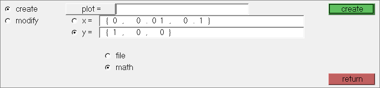
| 5. | Click create. HyperMesh generates a curve. |
Step 28: Create a sensor card
Sensors are implemented as properties in HyperMesh. In this example we refer to the curve defined in the preceding Help topic.
| 1. | From the Analysis page, click safety >> sensors. |
| 2. | In the name = field, enter sensor. |
| 3. | Click card image =, and select SENSOR. |
| 4. | Click create/edit.The Card Image dialog opens. |
| 5. | In the TITLE field, enter This is a logical function sensor. |
| 6. | Set Sensor type to logical function switch. |
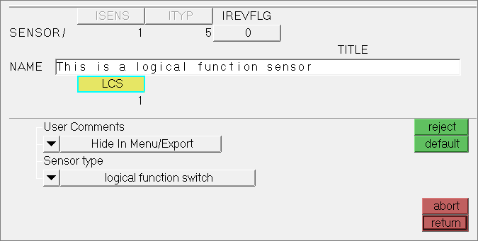
| 8. | Click return twice to exit the panels. |
Step 29: Exporting a PAM-CRASH 2G data deck from HyperMesh
This section explains how to generate a PAM-CRASH 2G input deck from HyperMesh.
| 1. | From the menu bar, click File > Export > Solver Deck. The Export - Solver Deck tab opens. |
| 2. | In the File field, enter rail.pc. |
| Note: | rail.pc is the PAM-CRASH2G file you will create. |
| 3. | Set Template to Pamcrash2G2007. |
| 4. | Click Export. HyperMesh writes the deck, and a message in the Status bar indicates the process is completed. |
See Also:
HyperMesh Tutorials


