The purpose of this tutorial is to illustrate the information and steps required to setup a SimLab model in HyperStudy. You will setup a mesh refinement study to investigate the relationship between SimLab mesh parameters, in this case the global element size, and the resulting maximum displacement.
The model used in this tutorial is a Parasolid CAD file of a connecting rod (ConnectingRod.xmt_txt). The connecting rod is loaded at one end, and constrained at the other. The output response of interest will be the maximum displacement.
The model has been used to record a SimLab project, which can be replayed using different parameters. The SimLab project file is named Conrod.sls. This file is dependent on several other files that were created during the recording process.
The files used in this tutorial can be found in <hst.zip>/HS-1610/. Copy the tutorial files from this directory to your working directory. The tutorial directory includes the following files:
| Note: | This HyperStudy - SimLab connection, requires SimLab version 13.3. HyperStudy will try to use the version of SimLab that was installed with the current version of HyperStudy. To direct HyperStudy to use a different version of SimLab, point the HW_HST_CMD_SIMLAB environment variable to the appropriate SimLab executable. |
|
| 2. | To start a new study, click File > New from the menu bar, or click  on the toolbar. on the toolbar. |
| 3. | In the HyperStudy – Add dialog, enter a study name, select a location for the study, and click OK. |
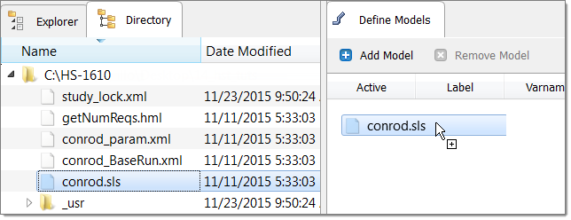
| 4. | Go to the Define models step. |
| a. | From the Directory, drag-and-drop the SimLab Session (.sls) file conrod.sls. into the work area. |
| b. | In the Solver execution script column, select OptiStruct (os). |

| 6. | Click Import Variables. Three input variables are imported from the SimLab Session (.sls) file. |
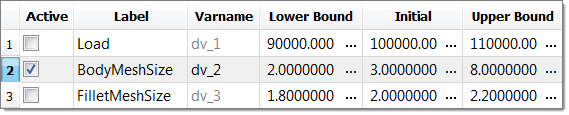
| 7. | Go to the Define Input Variables step. |
| 8. | Deactivate all input variables except BodyMeshSize. |
| 9. | Change BodyMesh Size's Lower Bound to 2.0 and Upper Bound to 8.0. |
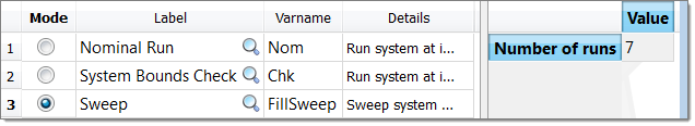
| 10. | Go to the Specifications step. |
|
| 1. | In the work area, set the Mode to Sweep. |
| Note: | In Sweep mode, HyperStudy runs system values from the lower bounds to the upper bounds. |
| 2. | Change the Number of runs to 7. |
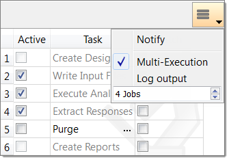
| 4. | Go to the Evaluate step. |
| 5. | Click Evaluate Tasks. An approaches/nom_1/ directory is created inside the study directory. |
| Tip: | If you have sufficient HyperWorks Units, activate Multi-Execution, and increase the number of simultaneous jobs to make the sweep study more quickly. |
| 7. | Go to the Define Output Responses step. |
|
| 1. | Create the maxStress output response. |
| a. | From the Directory, drag-and-drop the conrod1.h3d file, located in approaches/nom_1/run_00001/m_1, into the work area. |
| b. | In the File Assistant dialog, set the Reading technology to Altair® HyperWorks® (Hyper3D Reader) and click Next. |
| c. | Select Multiple items at multiple time steps (readsim), then click Next. |
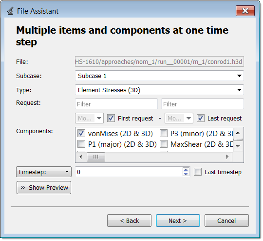
| d. | Define the following options, and then click Next. |
| • | Set Subcase to Subcase 1. |
| • | Set Type to Element Stresses (3D). |
| • | For Request, select the First request and Last request checkboxes. |
| • | Set Components to vonMises (2D & 3D). |
| e. | Label the output response maxStress. |
| f. | Set Expression to Maximum. |
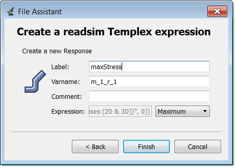
| g. | Click Finish. The maxStress output response is added to the work area. |
| 2. | Create the maxDisplacement output response. |
| a. | From the Directory, drag-and-drop the conrod1.h3d file, located in approaches/nom_1/run_00001/m_1, into the work area. |
| b. | In the File Assistant dialog, set the Reading technology to Altair® HyperWorks® (Hyper3D Reader) and click Next. |
| c. | Select Multiple items at multiple time steps (readsim), then click Next. |
| d. | Define the following options, and then click Next. |
| • | Set Subcase to Subcase 1. |
| • | Set Type to Displacement (Grids). |
| • | For Request, select the First request and Last request checkboxes. |
| e. | Label the output response maxDisplacement. |
| f. | Set Expression to Maximum. |
| g. | Click Finish. The maxDisplacement output response is added to the work area. |
| 3. | Click Evaluate Expressions to extract output response values. |
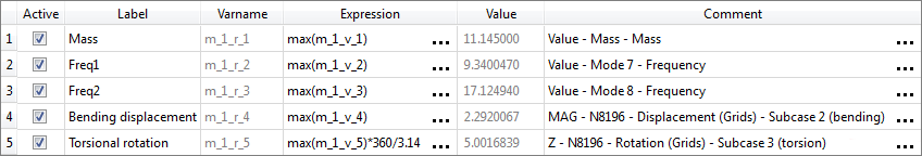
| 4. | Click OK. This complete the study setup. |
|
| 1. | Go to the Post processing step. |
| 2. | Click the Scatter 2D tab. |
| 3. | Using the Channel selector, set the X-Axis to BodyMeshSize and the Y-Axis to maxStress and MaxDisplacement. |
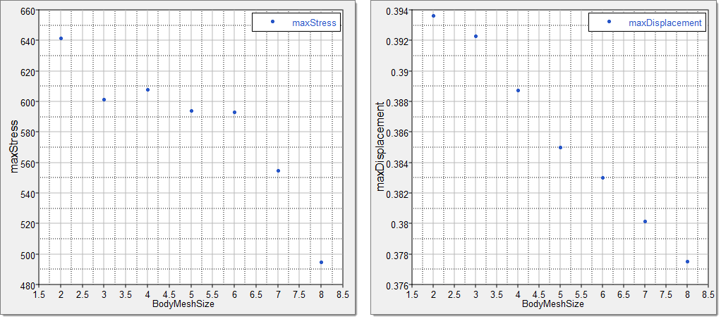
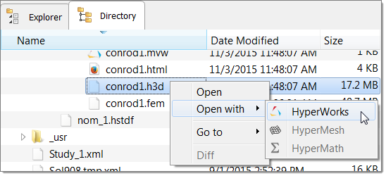
The results of the scatter plot indicate that as the mesh size gets smaller (moving along the x-axis to the left), displacement starts to converge. However, stress does not converge. This is typical in finite element models, as displacement will converge before derived quantities like stress. In this particular example, the stress output response may not converge at all due to the location of the maximum stress in the model (adjacent to the load application area). This can be seen by opening the resulting file in HyperView. To open the resulting file in HyperView, right-click in the study Directory and select Open with > HyperWorks from the context menu.
|
See Also:
HyperStudy Tutorials


