Bar/Beam 1D source elements to 2D / 3D target element mapping.
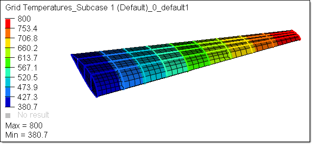
Resulting thermal distribution on 2D elements
|
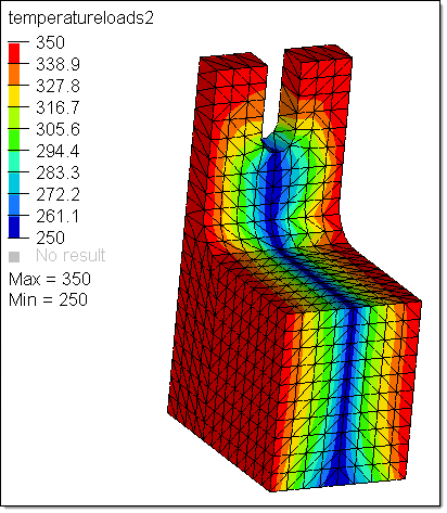
3D Source elements to 2D or 3D target elements including higher order source elements.
|
| • | Triangulation XYZ points based csv file based source data before mapping and using linear shape functions mapping (2D/3D target elements) |
| • | Inverse distance weighted mapping |
| • | Mapping target nodes falling outside the source elements using close point approach and the nodes falling inside the source elements using shape functions |
|
Generic field mapping using matrix columns (source data) and mapping to a new HW table for the target elements and exporting this table to Excel using matrix.
|
Transforming and reviewing of source nodes/elements data before mapping to the correct target elements.
|
Nodal Force balance mapping using OptiStruct to ensure the mapped target nodal forces and source nodal forces are in equilibrium.
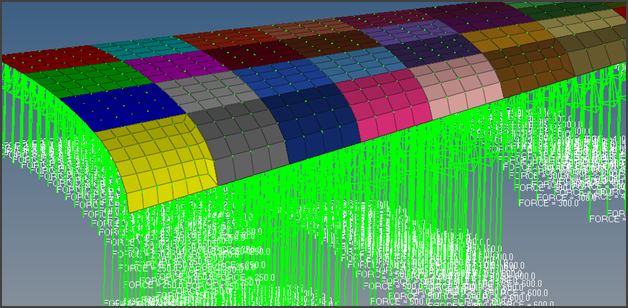
Source model nodal and mapped using OptiStruct to a new target mesh with force balance
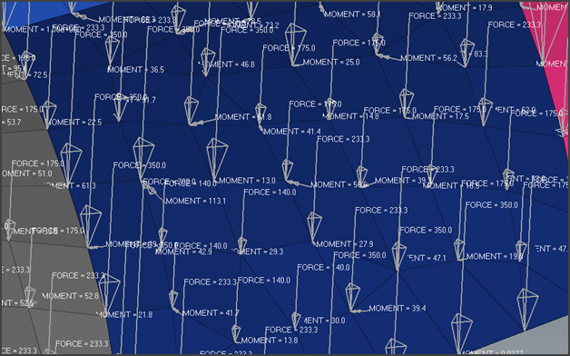
Target mesh nodal forces and moments from source nodal forces with equilibrium
|
A new connector type is added to Automate rivet creation from a CSV file.
This is an extension of the Hilock connection from connectors.
|
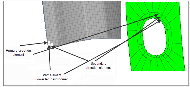
New element and nodal renumbering function is added.
This function requires users to select start element (or node) and adjacent connected elements (or nodes) to indicate primary and secondary directions. These elements needs to be connected.
Limitation of this method: This method works only with quadrilateral elements (without any triangular elements) and should have a mapped (regular) pattern.
|
HyperView Interface
An Aerospace Tools profile has been introduced to provide following functionalities:
| 1. | From the File menu, select File > Load > Preference File. The Preference dialog is displayed. |
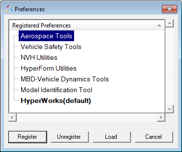
| 2. | Select Aerospace Tools and click Load. The Aerospace menu is displayed on the menu bar. |
|
The Result on Stack tool allows the user to display layer based shell results along the real stacking sequence of the selected element(s).
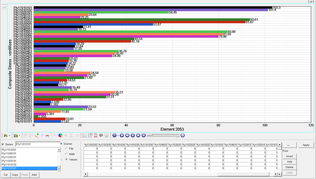
Result on Stack tool support the following solver profiles:
| 1. | OptiStruct (zone and ply based) |
|
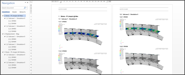
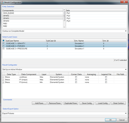
The Report Configurator tool enables you to quickly create either a Word document or pictures.
This option will generate a new chapter for each selected results. Each chapter will have a subchapter for each selected load case which then will have again a dedicated subchapter for each selected parts.
|
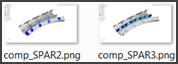
With this function, after selection of the configuration, you can input a destination directory in which the tool will create a subfolder for results then a sub folder for each load case and then an image for each selected part/set.
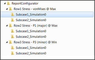
For example, this configuration:
Will generate the following folder structure:
|


