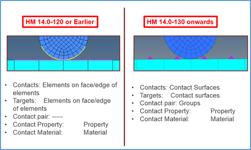
In ANSYS, solver contact surfaces are identified as elements overlaid on the faces of solid or shell elements that represent the geometry of the FE model. Prior to this release, HyperMesh followed the same principle as the solver to provide interface with ANSYS. Hence both CONTACT (defined as master in HyperMesh) and TARGET (defined as slave in HyperMesh) regions were elements over FE model that represent the geometry of the model.
This has been changed. Now these contact regions are no longer a set of elements in HyperMesh. Both contact and target regions are identified as CONTACT SURFACES. A pair of contact and target surfaces that interact with each other in analysis are defined by CONTACT PAIR in HyperMesh. Users needs to create contact surfaces for both CONTACT and TARGET regions. Then they are paired together under “Contact Pair” to successfully define the contacts. In the contact pair, users will define the element type for the master and slave. During export to the ANSYS solver file (*.CDB file), these surfaces will be converted to contact elements of type defined in contact pair. ANSYS solver files with contacts are imported in HyperMesh, which then identifies the contact regions from the contact elements and shows those regions as contact surfaces. Each contact pair is listed in the table area of the Contact browser.
The image below highlights the differences in support of contact surfaces from previous to current releases:
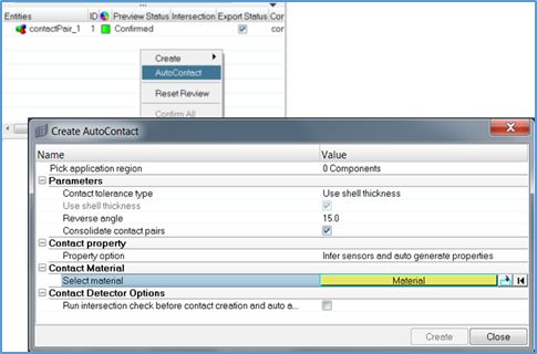
With this new contact support in HyperMesh, users can create surface to surface, edge to edge, point to surface and rigid (pilot node) contacts. To create point to surface contacts “contact masses” need to be defined for contact surfaces. Contact masses are node sets. To define rigid contacts with pilot node option users need to create a node set with single node in it. Options to create all these surfaces and node sets are available in the Contact browser.
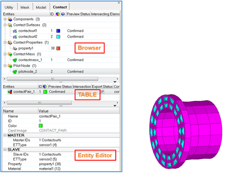
The Contact browser can list, create and manage contact surfaces and pairs in HyperMesh. All components in the model, contact surfaces, contact properties, contact mass and pilot nodes are listed in the browser. The table lists and creates the contact pairs, or guides user to use the Auto Contact tool. The Entity Editor shows the details of the entity picked in browser or table. The Contact browser, table and Entity Editor has many options that can be accessed from the context sensitive menus. More information is available on online help about these options.
Options to create symmetry contacts is available via the context sensitive menu on eligible contact pairs. Using this option creates a replica of the selected contact pair but the master (contact) surface and slave (target) surfaces are swapped.
Using this new contact support, users can review, adjust and reverse the normals of the contacts of both surface to surface (3D) and edge to edge (2D) contacts.
Please refer to the online help for more information on how to create contact surfaces and contact pairs.
|