|
»Click here to display Table of Contents«
|

HyperMesh |

|

|

|

|
|
HyperMesh |
|
|

|

|
|
»Click here to display Table of Contents«
|
HyperMesh |
|
|
|
|
|
HyperMesh |
|
|
|
|
General
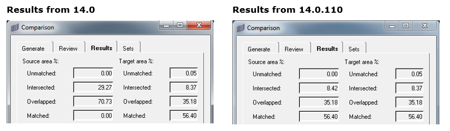
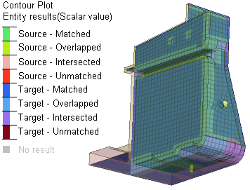
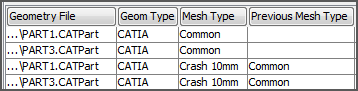
Improvements have been made to the accuracy of the 2D thick shell comparison for surfaces. For the revised thick shell calculations there is now a matched percentage for surfaces. Previously, overlapped was the maximum category and the matched percentage was always 0. The match types assigned to surfaces have not changed, though, so overlapped will remain the maximum category for display and there will be no matched surfaces shown. To make the calculation, the matched area for elements is divided by two. A similar thing is done with the overlapped category. The unmatched calculation is kept as-is, and the intersected category is adjusted to make sure that the percentages add up to 100%. In addition, if there is 100% matched for the FE, the surfaces are also set to be 100%.
|
H3D files exported from HyperMesh can now optionally contain match results from the Comparison tool.
|
|
Model Build & Assembly
The Common Model workflow has been significantly enhanced with respect to improved representation handling and improvements to entity management.
Representation Management Enhancements include automatic generation of the common representation, the ability to skip loaded representations when performing a Load representation operation, the introduction of a Reload representation operation, the reorganization of the representations context menu to logical group frequently used operations and an Add representation workflow enhancement which allows the addition of multiple representation simultaneously.
Entity Management Enhancements include the introduction of user editable PDM Metadata via the Entity Editor, enhanced entity update from PDM Metadata via the Update representation operation and PDM Metadata synchronization from HyperMesh entities via the Sync Metadata operation.
Connectors
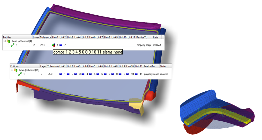
Grouplinks are supported for hexa seam and area connector absorption. During the absorption the top and the bottom side of the hexa connection is identified and the links are combined into one grouplink per side. This leads to more reproducible results during repeated realization because of distinct projections. A typical example is the absorption of the bondline of a windscreen.
|
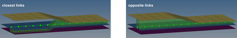
The Opposite Link option has been introduced for seam connector realization. If enabled it ensures that the closest links on both sides of the connector are connected. There is a link check which checks whether the links are parallel, this is called the normal projection deviation angle. This option assists the realization if the seam is not precisely positioned in between the connected parts.
|
The Remesh option has been enhanced and now works for quad seams. The new behavior ensures correct t-edges and prevents the creation of free edges. The mesh quality has been improved as well. This option is especially useful for areas of the model with close quad seams, where the quad transition may have conflicts.
|
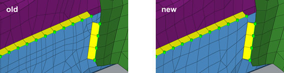
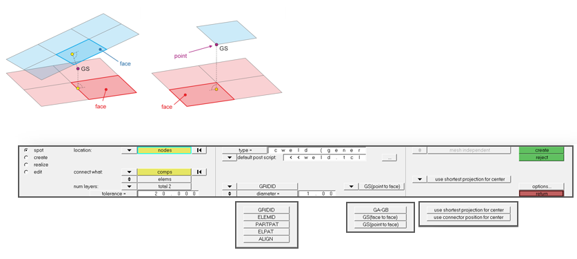
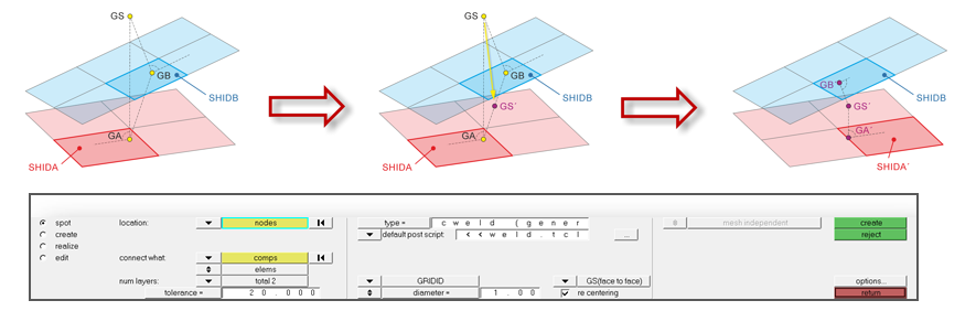
All CWELD realization types have been consolidated to one CWELD (general). CWELDs with GS node definition do support face to face as well as point to face connections.
CWELDs connecting faces and defined with a GS node can be recentered. The projections are revalidated then.
|
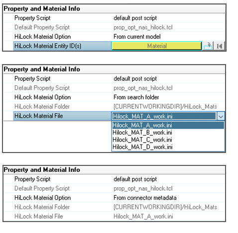
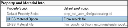
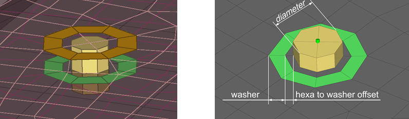
Once a connector is set as being a HiLock connector, different HiLock Material Options can be set per connector basis in the Connector Entity Editor. If the connector has been realized as Hilock Material before, a material can be selected from the current model from a specially defined folder or from metadata.
|
This realization creates hexa clusters between shell components and connects them via contact definitions. For components of certain materials a heat affected zones is imprinted into the shell mesh. The materials which get the special treatment can be automatically defined by names in a file or by selecting from the model.
|
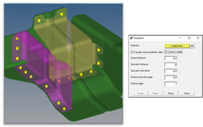
The autopitch functionality has been enhanced to consider closed shell thin solids. When enabled, allows shell meshes that enclose a volume (some small gaps are allowed) to additionally be used as input for the connector creation.
|
Connectors now support unique part identifiers (UID) as links.
|
|
Geometry
|
Meshing
|
New options added to have more control over the SPH generation process. Definition of mesh orientation will enable you to generate mesh aligned with model coordinates. With new options to select volume to be filled, you can generate SPH particles in specific volume domain. Partial filling option will enable you to define the level till SPH particles to be generated. You can define wall clearance and wall offset setting for generating SPH according to physical requirements.
|
|
HyperMorph
|
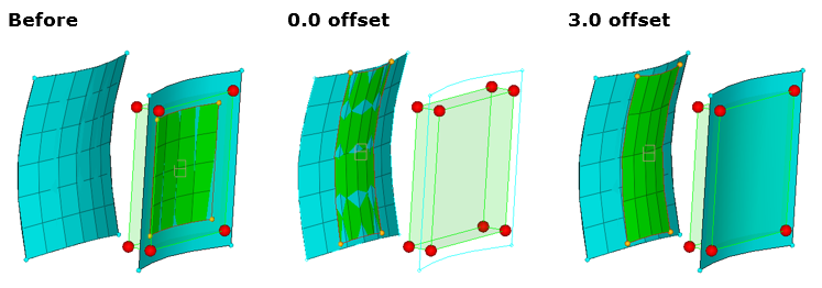
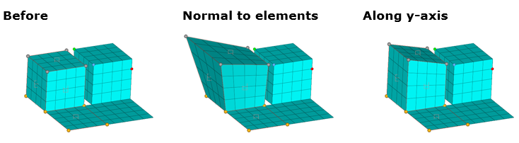
A new along DOFs constraint type is now available. This enables the constraint to fix one, two or all three degrees of freedom for a node relative to a local coordinate system, or to the global coordinate system. During morphing, the coordinates along the specified DOFs will remain fixed, while the others are allowed to change. For example, fixing nodes in the r DOF of a cylindrical system will cause them to remain a constant distance away from the z-axis of the coordinate system.
|
When shrinking morph volumes, a new implicit method is available (in addition to the legacy method, now named explicit). This new method is generally faster and more robust than the legacy method, although it does usually require twice as many iterations to converge. The implicit method is now used when morph volumes are created and the shrink mvols option is selected.
|
|
|
|
APIs
|