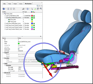
The Mechanism Tool, available in the RADIOSS and LS-DYNA user profiles, enables the modeling of kinematic systems by the definition of kinematic assemblies (bodies) and kinematic joints. The definition of the mechanism is made in a dedicated browser, with the Entity Editor for the related mechanism entities (Mechanism, Body, Joint, Constraint). The usage of manipulators offers a powerful user interaction with the mechanism.
This tool is especially useful for seat mechanism application, for which a kinematic coupling with a dummy is possible. The Mechanism Tool can also be used to model any kind of kinematic system.
|
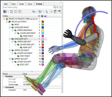
A new Dummy Positioner is available in the RADIOSS and LS-DYNA user profiles, to position a dummy interactively. The dummy positioner is now integrated in a new browser, with interactive manipulation of the joint from the graphics. The Dummy Positioner is compatible with all LS-DYNA and RADIOSS Humanetics dummies (encrypted or not) and also with LSTC LS-DYNA dummies.
|
| • | XML comments and CSV Support |
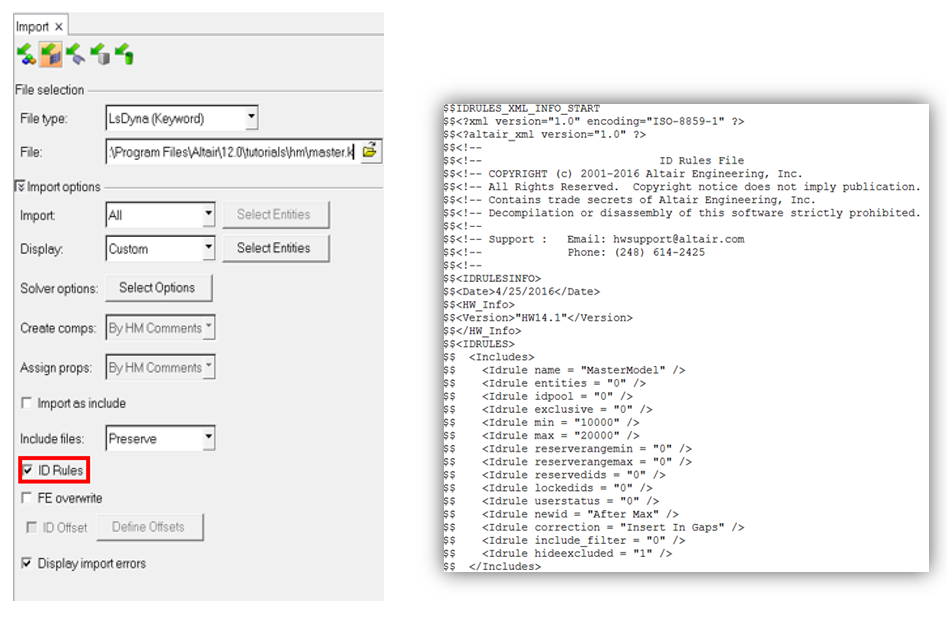
Import and export of ID Manager rules as XML comments in the solver deck is now supported. A new ‘ID Rules’ check box is added in both Import and Export browser tabs as well as in the Include View when you export an include file or all includes.
The XML comments are written as a separate block at the end of a solver deck similar to connectors XML comments export.
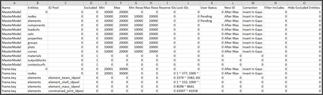
You can also save ‘ID Rules’ in a CSV file directly from the ID Manager dialog. This new setup is available in the context menu of ID Manager Dialog. Both Import and export of CSV file is supported.
| • | Filtering Includes and Hiding Excluded Entities |
The ID Manager dialog has added a Filter include file button that enables you to set a filter on the available includes. The filter button will dynamically update the status from default OFF to ON when filtering is applied.
You can also now hide excluded entities in the ID Manager dialog. The check box works across the includes and hide entities from the dialog if they are shown as excluded entities.
Both Include Filtering and Hide Excluded Entities settings can be saved and read using the HM model and the solver deck, respectively.
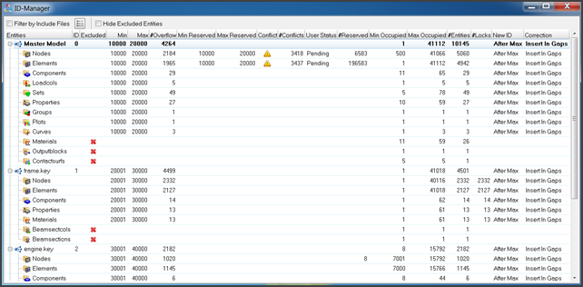
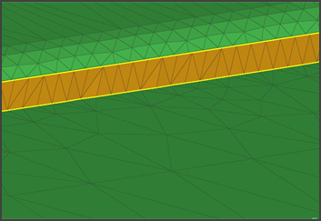
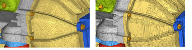
Before applying Filter Include and Hide Excluded Entities settings
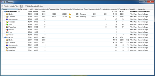
After applying Filter Include and Hide Excluded Entities settings
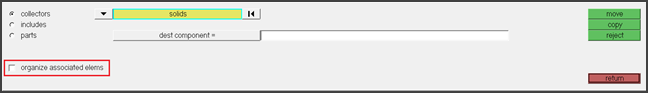
| • | Ability to organize associated elements while organizing solids geometry |
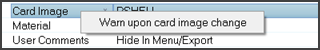
| • | Warning message setting inside Entity editor for change in card image is now off by default |
|
Undefined Entity support is extended to Sets and Curves for all applicable User Profiles. In addition, a warning message is displayed in the Import Process Messages dialog on the import of a solver deck containing referenced entities.
|
The import and export of referenced entities is fully supported for properties, materials, sets and curves. HyperMesh creates the appropriate entities and assigns a default Card Image upon import of a solver deck containing referenced entities. In addition, a warning message is displayed in the Import Process Messages dialog on the import of a solver deck containing referenced entities.
Undefined entities exhibit the same behaviors as defined entities; they are visible in all relevant browsers and in the Entity Editor. The defined state, attributes, and Card Image can be modified as per requirements of the user.
The renumbering of undefined entities is restricted to ensure references to entities that reside in external Include files will not be invalidated.
|
Enhanced Undo Redo support which now includes additional panels, browser operations and improved messaging.
|
DDAM interface has been enabled via the OptiStruct user profile.
|
The ability to control comments – HM, ID Rules, Part Assembly/Part, Connectors – has been added within the include export operation from within the Browser Include view. These same options are available via the standard export.
|
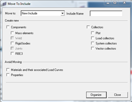
The Move to Include capability is now supported for the RADIOSS user profile in addition to Ls-DYNA. The capability enables the component and all of it’s referenced and cross referenced entities to be organized (moved) to the selected include or new include.
|
In the Organize panel, you can now select to organize the solid elements associated with solid geometry.
|
Several updates were added including improved handling of meshless welds (connectors), improved messaging, better support for *PART_COMPOSITE replace plus the resolution of several issues including the direct property assignment to solid elements being lost post part replace.
|
The Count panel now has new widgets for counting topo points (vertices) and topo lines (surface edges). This is in addition to the existing widgets for counting free points (points) and free lines (lines).
| • | Improved Accuracy for mass calculation |
New FIND CONNECTIVITY tool available to identify portion of a model that are not connected
|
| • | Missing option related to connector’s comments while exporting an include file. |
| • | Saved Views in the browser are getting messed up after renumbering and reordering components. |
| • | Preserved nodes are unexpectedly getting selected during any nodes selection operation. |
| • | Organizing a component to an include is not working consistently. |
| • | Deleting unused sets from delete panel also delete the rigid bodies. |
| • | Application crashes while using hm_createmark API for curves. |
| • | Model Checker rerun automatically if you clear the session and reload the model again in the same session. |
| • | Export an include with relative path crashes the session. |
| • | Mass value of individual Include file imported with master is showing wrong value. |
| • | Fixed a refresh problem in the Solver browser that was not listing a newly created system. |
|
The Common Model workflow has been significantly enhanced with respect to Representation Management and Configuration Management.
Representation Management Enhancements include the one click generation of all representations, the introduction of the Representation Settings dialog for organization of user defined representations and an Add Representation workflow which allows automatic loading of added representation added in bulk and the filtering of associated representation files.
Configuration Management Enhancements include the introduction of two new HyperMesh entities, Part Sets and Configurations, the former facilitating the logical grouping of Part Assemblies and Parts and the latter facilitating the creation of user defined configurations. In addition, the introduction of multi-pane views and an intuitive drag and drop workflow in the Part browser simplifies the creation and organization of multiple configurations in a single HyperMesh binary file. Figure 1 shows a sample BIW subsystem with multiple configurations.
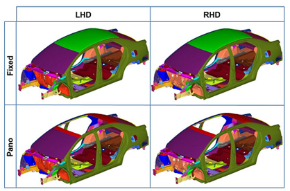
Figure X: BIW Configurations
The image below shows Configuration multi-pane view in Part Browser for the BIW model.
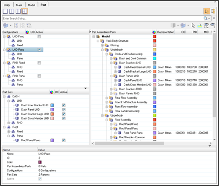
Figure 2: Part Browser – BIW model
Connectors
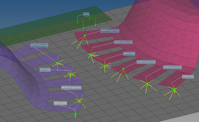
On the visualization tab in the connector chapter a special CWELD visualization can be activated. The graphical representations reflect the different CWELD definitions.
|
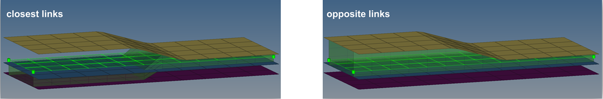
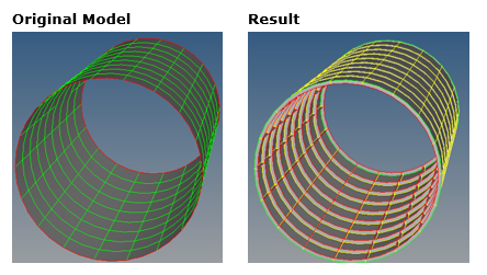
The opposite link option has been utilized for the area connector realization. If activated it ensures, that to both sides of the connector the closest link candidates are connected. The parallelism of the opposite links is check and controlled by the definable normal projection deviation angle. This option helps to realize in the desired way, if the seam is not precisely positioned in the middle of the connected parts.
|
The complete absorption has been performance improved. Along this update couple new mechanisms have been implemented:
ACM (general):
All regular ACMs will be absorbed as ACM (general) now. During the absorption three versions are differentiated (shell gap, equivalence (T1+T2)/2), constant thickness). The connector get the appropriate attributes assigned, which allows the same rerealization.
For certain situations there isn’t a clear identifier between shell gap and equivalence (T1+T2)/2. The new option If hexa thickness type is ambigous decides about the preference.
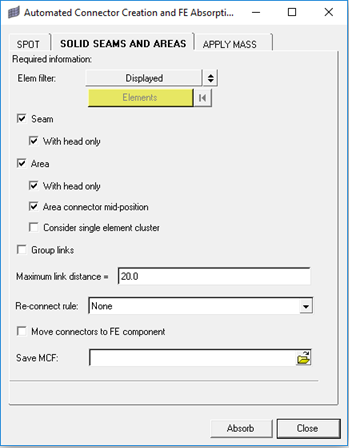
Solid seams and areas:
The absorption of solid seams and area connectors can be more precisely controlled. It is clearly differentiated between seams and areas, as well as between with head and without head.
|
In the context menu of the Connector browser, connectors of one specific style can be converted into another one. This has been enhance in a way, that additionally any connector lines can be converted to seam connector lines and vice versa.
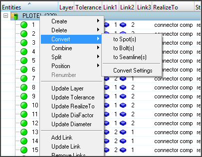
Convert settings control, if line connectors should remain as line connectors after the conversion or if they are going to be converted to single point connectors pro each connector point.
|
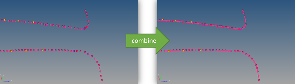
In the context menu of the connector browser aligned single point connectors can be combined into line connectors of the same style or several aligned seam line connectors into larger one(s).
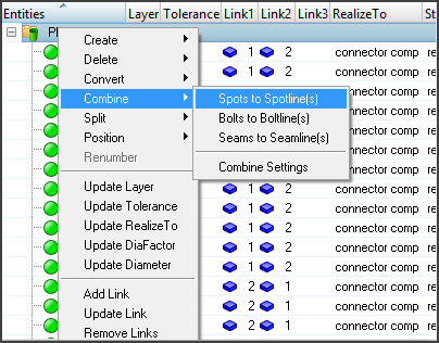
In the combine settings an angle and a distance is defined, which describe the conditions for combining single point connectors.
|
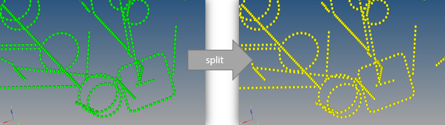
In the context menu of the Connector browser, spot or bolt line connectors can be split into individual single point connectors.
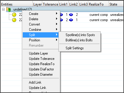
In the Split settings, it can be decided if the connectors should be unrealized along with the split.
|
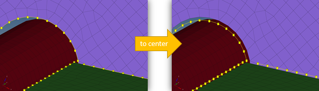
In the context menu of the Connector browser spot or seam connectors can be positioned to the center position between the defined link candidates. The source position is stored on each individual connector; hence moving back to the source position is possible, too.
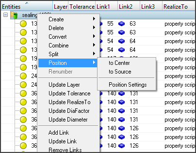
In the position settings the selected connectors can be filtered down with respect to certain attributes.
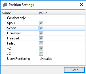
The position function works for single point as well as for line connectors.
|
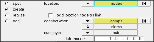
In the Spot panel for connector creation and realization the number of layers can be set to auto now. The precise number of layers will be detected during the link detection process and saved onto each individual connector. A reasonable tolerance is essential, when using auto for the number of layers.
|
For connector import overwrite and ID offset is supported now.
|
| • | Looped seam connectors created by nodepath were only visually closed. |
| • | Weighting factors for the ACM (general) realization with radius option and normal distribution was wrongly calculated. |
| • | Inactive components weren’t ignored during absorption. |
| • | For CWELDs GS (point to face) the GS node wasn’t equivalenced to the link. |
| • | The connector XML import for big area connectors led to a crash. |
| • | Several attributes in the Connector Entity Editor were not available. |
| • | In certain cases bad hexa elements have been created for adhesive seams in combination with discontinuity. |
| • | Seam snapping behaved wrong in some scenarios. |
| • | For more complex shapes the area connector has been created wrongly. |
|
Geometry
The Dimensioning tool has undergone significant changes to improve the workflow and the usability.
A new Feature entity has been added, which allows defining, storing and manipulating relevant geometric dimensions in the model from within the browser, and via Tcl APIs. In addition, dimensions can also be parameterized via the parameter entity, as well as linked together via parameter entity expressions. This allows for easy design optimization iterations with HyperStudy. Previously, the dimensions only existed and could only be controlled within the Dimensions panel.
General improvements have also been made to the robustness of the tool.
|
This tool, accessed from the Geometry menu, fixes gaps between stitched edges and vertices to make the actual geometry of the surfaces consistent with the model topology. It checks the topology of the model for gaps that are larger than a given tolerance between shared, non-manifold, or suppressed edges. If a gap is found to be bigger than the specified tolerance, then the surface and edge geometries will be morphed parametrically and in 3D, if necessary, to make the gap smaller than the tolerance. In addition, non-essential degenerate edges are removed.
|
In order to increase the performance of the Surface Edit > Trim with Lines > With Lines panel for aerospace use cases where many free lines are being used to trim surfaces, a few improvements have been made:
| • | Implemented choices for the type of line to use as input, so that the user can easily select only free lines (default), only surface edges, or any lines. |
| • | Changed the default maximum projection distance to match the geometry cleanup tolerance (previously the default value was zero). |
| • | General improvements to the trimming performance. |
When utilizing these options together, improvements on the order of 30-40% may be seen.
|
A new subpanel Surfaces > Normal from Edges has been added. This allows the creation of surfaces by dragging lines along the normal of their adjacent surfaces. This is useful for creating ribs and spars in aerospace models.
For shared and non-manifold edges, the surface normal is taken from the surface of the master edge. In the event the neighbor surfaces are tangent enough to each other, the average normal is instead used. Adjacent surfaces are properly trimmed and stitched together to allow for a simple one-step process.
|
| • | The geometry feature angle can now be specified between 0-180 degrees for face selection, instead of being limited to 0-90 degrees. |
| • | The duplication of surfaces now properly maintains any suppression of fixed points from the original surface to the duplicate. |
| • | Metadata is now maintained and propagated when performing surface offset and dimensioning. |
| • | Suppressed lines are now supported for selection "by path". |
| • | The Surfaces > Meshline subpanel has been fixed to resolve multiple issues and crashes. |
|
| • | Resolved an issue with CAD metadata handling causing a crash on HyperMesh binary save and/or load. After merging two or more CAD files containing metadata into the same session, saving the HyperMesh binary file would potentially result in a crash. If the save was successful, those files would potentially crash upon load. These issues have all been resolved. Any existing binary files that exhibited the crash due to this issue can also now be successfully loaded. |
| • | Resolved an issue where under certain conditions, an invalid topology was created during CATIA composites import. This would potentially lead to a crash upon saving or loading the HyperMesh binary file. These issues have all been resolved. Any existing binary files that exhibited the crash due to this issue can also now be successfully loaded. |
| • | When trimming surfaces that had suppressed edges, sometimes the suppressed edges would become unsuppressed, or would have vertices created at the trim line locations. These issues have both been resolved. |
|
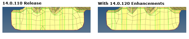
| • | Updates have been made to improve the meshing of flanges. These include: |
| - | Suppressing unnecessary input edges to improve mesh flow |
| - | Preventing the addition of unnecessary trim lines that may disturb mesh flow |
| - | Removal of narrow elements that disturb the mesh flow |
| - | These enhancements do not require any changes to the param file |
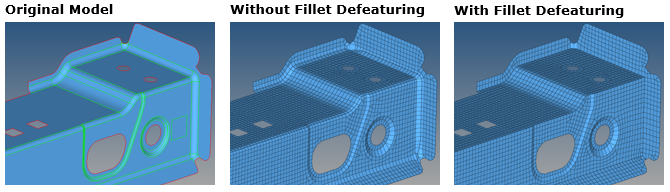
| • | The ability to defeature fillets has been added to the surface fillet table. This allows for the removal of fillets that fall within certain ranges. Additionally, special geometry cleanup is performed after defeaturing in order to cleanup any unstitched edges, and to patch any holes or gaps. |
| • | Plot elements associated to surface edges are now maintained and used for connectivity within BatchMesher, instead of being deleted. Other 1D element configs were previously supported. |
| • | When the mesh type is set to trias, the meshing of rectangular surfaces no longer results in a majority r-tria mesh. |
| • | Miscellaneous minor bug fixes related to the feature recognition and capture of beads, fillets and holes. |
|
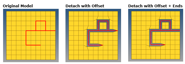
A new detach capability, useful for creating faults for geomechanics, has been added which allows detaching elements from the nodes of wall elements. This is available via the Detach > From Wall subpanel.
The elements surrounding the wall must be one dimension higher than the wall elements. The elements surrounding the wall can be classified as belonging to different clusters based on which side of the wall elements they appear. For each cluster of elements attached to the wall, the shared nodes are duplicated after detachment.
Options are also available for offsetting the nodes of the detached elements, as well as also detaching the free ends of walls.
|
The Volume Selector in mesh controls allows you to select volumes based on enclosed seed node. You can define fluid volume and solid volumes by selecting enclosed seed node. Also, you can define which volume should be skipped by selection enclosed seed node.
You can also define index of the volume to be meshed as largest, 2nd largest, etc.
|
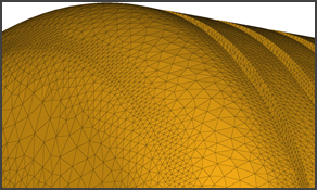
The Surface Deviation method for element remeshing can be accessed now via the Automesh panel. It captures curvature and provides smooth transition from small size elements to big size elements. A new mesher internally identifies the elements features based on defined feature angle and captures/refines them.
|
| • | Option to create patch in imprint: |
A new is available in the Imprint panel which creates a patch between imprinted edges. This enables you to retain the inputs as they are and create patches in-between rather than merging them.
| • | Option to select nodes as source: |
You can now can select nodes as source in the Imprint panel. This enables you to imprint nodes on edge to imprint on element faces without creating 1D elements.
|
| • | Added support for bar3 element creation in the Line Mesh and Linear 1D panels. |
| • | The Preserve Edges tool can now be accessed directly from the Autocleanup panel and the Automesh > batchmesh/QI subpanel. |
| • | Element normals can now be adjusted using a reference vector direction within the Normals panel. |
| • | The connectivity between 2D element edges and 1D/3D elements can now optionally be maintained in the Elem Cleanup panel. |
|
| • | Mesh controls feature-based meshing issues related to several crashes, incorrect/incomplete fillet meshes, and mesh connectivity problems when using standalone feature-based meshing (without other HyperMesh mesh controls) have been resolved. |
| • | When creating a mesh in the Line Mesh panel and specifying an orientation node, all beam elements in the model were being updated to have this orientation node. That has been resolved. |
| • | When using QI or BatchMesher meshing with the mesh type set to trias, the meshing of rectangular surfaces no longer results in a majority r-tria mesh. |
|
All CAD import and export options can now be specified on the command line via the new *geomimport and *geomexport commands, as well as within the respective .ini files. This allows for complete customization of the CAD import/export behaviors from within a Tcl script.
When legacy commands *geomoutputdata, *geomoutputdata2, *iges_write or *iges_write_units are executed via scripts, *geomexport will be written to the command file instead.
|
The HM_COMMANDFILE_MODE environment variable has been enhanced. When using UNIQUE mode, the user name is now also included in the command file name, to further guarantee uniqueness and to allow for better traceability.
|
New options have been added to *createmarkpanel and *editmarkpanel:
| • | New node face/edge selection modes free edges ext (6) and edge ext (7) for face_edge_mode. |
| • | New filter option for specifying only specific selection modes to allow. |
In addition, hm_formnodelistsfrommark has been added for converting a mark of nodes into one or more node lists.
|
A new API hm_getgeometricthinsolidinfo has been added for finding thin solid geometries, and returning information such as the estimated thickness and the master, slave and thickness surfaces.
|
Decimation APIs has been added to this version. Decimation APIs enables you to decimate (coarsen mesh) while retaining topological shape as it is while reducing element count. It will automatically detects curvatures and retain them. A new capability to define localized wrap settings via the Mesh Control browser is available. Local controls will take the precedent over global settings.
|
| • | Resolved an issue with the hm_framework removetab API in HyperMesh Desktop. Previously, any user-created frame would be destroyed during this call. This was inconsistent with HyperMesh standalone, where the frame would not be destroyed. An additional flag has been added to support also keeping the frame for HyperMesh Desktop. |
|


