General
|
A new Quick Access tool is added in HyperMesh (only) to easily create new solver cards or directly access functionalities. The tool is accessed by using CTRL+F shortcut key. The tool will populate as text is entered. Quick Access appears on the top right corner as shown in the images below: Quick Access can be dismissed by pressing the Esc key or just by clicking outside the tool.
|
The Element Thickness View now has two modes; discrete and ranged. If the number of different thicknesses is below 25, a discrete, categorized legend is shown by default. In the discrete legend, each thickness gets a dedicated color assignment. If there are more than 25 thicknesses, are a ranged legend is shown. All colors are editable and the values in the ranged legend can be modified. Both legends come with a slider which allows for the modification of the threshold value. Every thickness beyond the threshold value shown in transparent or wireframe. |
When performing a thickened shell mesh to 3D CAD comparison, the shell thickness is now taken into account for the distance contour and output results |
Performance and accuracy improvements New developments in the kinematic solver lead to important performance improvements especially for following features:
Support of mechanism and dummy in *INCLUDE_TRANSFORM In LS-DYNA profile, a mechanism and/or a dummy model can now be defined in a *INCLUDE_TRANSFORM card.
|
|
|
Connectors
A Query Builder has been added to both parts of the Connector browser. The Query Builder filters the link and connector lists dependent on their attributes. The value next to each folder describes the number of returned filtered entities along with the total number of entities of that type. When performing a show, isolate or find operation, the link entity list and the connector list can be dynamically filtered to return only what’s displayed. The last review filter can be reused and also combined with other attribute filters. The connector symbol signals whether the connector is displayed or not. By clicking on the connector icon it will change from full (displayed) to light (masked).
|
For area connectors, the projection control method can be defined via the Connector Entity Editor. This new option enables more precise control over how the projection is handled. With these controls the realization of adhesive beads is significantly improved.
|
|
|
Geometry
Logos that span across multiple base surfaces are now successfully removed. In addition, a new “auto” mode is available for automatically detecting the logo height and width to remove. |
|
Meshing
|
|
|
HyperMorph
For the options "map to surfaces" and "map to elements" there is now a checkbox labeled "extend edges." When checked, this option will map any nodes which would have fallen outside the surfaces or elements to points perpendicular to the edges of the surfaces or elements, allowing the user to map nodes, elements, mvol edges, or mvol faces beyond the edges and inside holes. The same option is available in the Freehand panel under "move nodes" for the "move to surface" and "move to mesh" options.
|
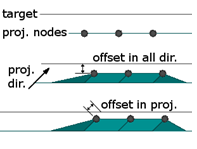
For the options "map to line," "map to node list," "map to plane," "map to surfaces," "map to elements," and "map to equation," there is now a toggle underneath the "offset = " field which allows you to select between "offset along proj." and "offset in all dir." For the former, any offset will be measured along the direction a node is being projected to the target. For the latter, any offset will be measured from the nearest point on the target. The same option is available in the Freehand panel under "move nodes" for the "move to vector," "move to node list," "move to line," "move to plane," "move to surface," and "move to mesh" options.
|
APIs
|
|