HyperWorks Release Notes

MotionView

MotionView

Previous topic Next topic Expand/collapse all hidden text  

MotionView

Previous topic Next topic JavaScript is required for expanding text JavaScript is required for the print function  

Highlights


hmtoggle_arrow1Use CAD Feature Recognition for Picking

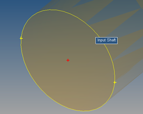
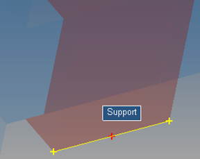
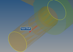
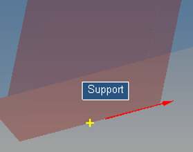
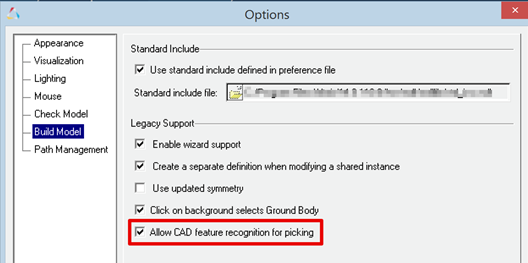
MotionView now provides the ability to use geometrical features such as edge and surfaces while creating entities. Through this feature, an edge or a surface of CADGraphics and primitive graphics such as Box and Cylinder can be used to pick origin or alignment axis for entities such as joints, bushings and forces. A point or a vector entity would be automatically created and resolved into the Entity panel.

mbs_14_110_01

Point at circle center

mbs_14_110_02

Point at edge center

mbs_14_110_03

Vector at axis of cylindrical surface

mbs_14_110_04

Vector on edge

While picking the point/vector, hover the mouse on the edge/surface to highlight it. While picking a point, a red cross mark + indicates the location of the point being created if clicked. Yellow cross marks + indicate other potential location on the edge.

To use this feature, the option “Use CAD feature recognition for picking” needs to be turned on through Tools > Option > Build Model.

mbs_14_110_05

In addition, this option enables:

-Highlighting of graphics in the graphics area under mouse cursor relevant for selection of entities
-Dim non-relevant entities during selection
hmtoggle_arrow1Improvements to Non-linear Finite Element Bodies

MotionSolve 14.0 introduced the “NLFE Body” as an experimental feature, which allows you to model non-linearly flexible beams and cables in your multi-body system. The NLFE Body is based on the Absolute Nodal Coordinate Formulation (ANCF). Nonlinearity can occur for two main reasons: (A) Geometric nonlinearity and (B) Material non-linearity. The NLFE body supports both. MotionView also introduced NLFE subsystems to model stabilizer bar and a helical spring system.

This release includes a more robust functionality for the NLFE in MotionView. The following improvements have been implemented for this release:

You can now specify the maximum allowable von Mises strain for your NLFE component in the model that can be set in MotionView using the Materials dialog.
MotionView now allows you to define a global method of attaching a marker to an NLFE body for defining joints, forces, bushes etc. This is achieved by defining an environment variable HW_NLFE_CONN_TYPE. You may specify up to six characters that determine how the additional 6 degrees of freedom at the NLFE attachment grid are to be constrained. For example:
-HW_NLFE_CONN_TYPE = TTTTTT implies that the marker is fully clamped to the grid. The grid cannot be subjected to any axial or shear strain. This is the recommended value.
-HW_NLFE_CONN_TYPE = FFFTTT implies that the marker is partially clamped to the grid. The grid can only undergo axial deformations but no shear deformation.
-HW_NLFE_CONN_TYPE = TTTFFF implies that the marker is partially clamped to the grid. The grid can only undergo shear deformations but no axial deformation.
-HW_NLFE_CONN_TYPE = FFFFFF implies that the marker is not clamped to the grid. All deformations are allowed on the grid.
-For more details, please see the documentation on CONN0 in the solver reference manual.
Issues related to calculations of CG and Inertia for different beam cross sections have been addressed.
The ROD and TUBE sizes were wrongly displayed in MotionView graphics area. This issue has been resolved.
A crash issue when invalid values are specified for no. of segments for ROD and TUBE sections is resolved.
MotionView now can identify the correct GRID that needs to be used when an entity attached to the NLFE body at that location uses a coincident point not part of NLFE connectivity.
An option to insert/delete a point between 2 existing connectivity points is now available.
Creating displacement/velocity/acceleration outputs on NLFE body is available. MotionView attempts to measure output at the CG location of the body. If a connecting point at CG is not available, the output at a location closest to the CG is created.


hmtoggle_arrow1Improvements to 3D Rigid Body Contact Solution
The Automated report available for a contact simulation is updated.
-The animation of forces page appears before the Contact Overview page
-The issue of end time setting to 1 s irrespective of the simulation time is resolved
-The force animation shows region output instead of force on each element
hmtoggle_arrow1New Air Spring Entity

A new air spring model is available as an Auto Entity in MotionView.  The air spring force is interpolated from a table of force verses spring height and static inflation pressure, which is typically published by spring manufacturers. You enter the spring trim load and trim height and MotionSolve calculates the static inflation pressure automatically. You may include a bumpstop with the air spring as well. The air spring and bumpstop force properties are read from TeimOrbit format property files.

To add an air spring to your MotionView model:

Load the Vehicle Dynamics Tools preference file by picking Load > Preference File from the File menu in MotionView and then selecting the MBD Vehicle Dynamics Tools preference file.
Right click on the model in the browser and from the context menu pick “Add Auto Entity” to launch the Add Entity dialog.
In option menu on the Add Entity dialog pick “AutoAirSpring”, select single or pair, and click OK.


hmtoggle_arrow1New Full Vehicle Kinematics and Compliance Event Documentation

The Full Vehicle Kinematics and Compliance Event available via the task wizard in MotionView is now documented in the online help under the topic
MotionView > Vehicle Dynamics Modeling > MDL Library User's Guide > Vehicle Modeling Library User's Guide > Events.


hmtoggle_arrow1Enhanced Tire Entities

The Auto Entities for MF-TYRE/MF-SWIFT, FTIRE/HTIRE, and CDTire now support offsetting the wheel/tire CM along the spin axis. A positive offset moves the CM outboard from the vehicle X-Z-plane.  In addition you can offset the wheel hub graphics as well.


hmtoggle_arrow1Updated FTire

COSIN FTire shipped with MotionSolve 14.0.210 is updated to version 2016-1. However, in the future releases of MotionSolve, FTire binaries will not be included. Altair recommends obtaining FTire from COSIN and installing FTire independently of MotionSolve. When you run FTire with MotionSolve, the COSIN initialization file (e.g. cosin_2016-1.ini) is read to identify the FTire installation, so you can be assured that the latest installed version of FTire is used.

 
Note: Using FTire 2016-1 with MotionSolve 14.0.210 requires a COSIN initialization file in your home directory.


hmtoggle_arrow1Other Improvements in MotionView
It is now possible to fit the screen display using the keyboard shortcut “f”
MV-HST – The Import Model Parameters dialog now shows only the active systems and analyses
MV-HST – An issue with active analysis not being selected by default has been resolved
User defined properties are now available for Plant Input and Plant Output solver array
Template of type USER & ADAMS can be evaluated prior to all other entities using the MDL *Set statement. For e.g. *Set(varname.pre_evaluate, true) where varname is the variable name of the template entity


hmtoggle_arrow1Resolved Issues
An issue of “Add Contact” context menu not appearing for the Contacts folder in the Projects Browser has been resolved. This issue was observed when the model contained only PointtoDeformableSurface contact
A rounding off error in direction cosine calculation for markers while using Euler Angles for orientation is resolved
User defined properties can now be used with Solver Array – Plant Input and Plant Output