HyperWorks Release Notes

MotionView 14.0.120 Release Notes

MotionView 14.0.120 Release Notes

Previous topic Next topic Expand/collapse all hidden text  

MotionView 14.0.120 Release Notes

Previous topic Next topic JavaScript is required for expanding text JavaScript is required for the print function  

Highlights


hmtoggle_arrow1Non-linear Finite Elements

Version 14.0 introduced the experimental feature “NLFE Body” which enables you to model non-linearly flexible components in your multibody system. Version 14.0.120 marks the formal release of the NLFE.

A generic NLFE Body can be created using either the BEAM or CABLE element. The NLFE Body is based on the Absolute Nodal Coordinate Formulation (ANCF). Nonlinearity can occur for two main reasons: (A) Geometric nonlinearity and (B) Material non-linearity. The NLFE body supports both.

Refer to MotionView User Guide and MotionSolve Reference Guide for more details.

The NLFE features available in earlier version have certain improvements.

MotionView now supports providing number of fibres information for Cable elements
An additional set of constraints CONN0 are introduced by default at NLFE grids that are associated with markers to rigidify the grid. The constraints are of the form <CONN0 id = “conn_id” gid = “grid_id” conn = “TTTTTT” />. The statement constrains the gradient vector. First 3 keywords ‘T’ in the conn attribute represents constraint on the gradients along X, Y & Z direction while the remaining 3 ‘T’ represent constraint in the rotational (shear) direction. The form of these constraints can be changed using an environment variable HW_NLFE_CONN_TYPE = ssssss, where s can be either ‘T’ or ‘F’


hmtoggle_arrow1Subsystems

Version 14.0 introduced “NLFE Subsystems” in an experimental form along with the NLFE body. The NLFE Subsystem contain tools to create an NLFE based stabilizer bar and helical spring. In this version, the toolbar “NLFE Subsystems” has been renamed as “Subsystems”. Along with NLFE, the experimental tag on the Subsystems is also removed. In addition, a belt pulley system creation tool is made available.


Belt Pulley System

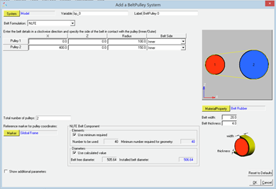
A belt-pulley system can now be assembled quickly using the Belt-Pulley Subsystem tool available within the Subsystems toolbar

Two types of belt modeling methods are now available
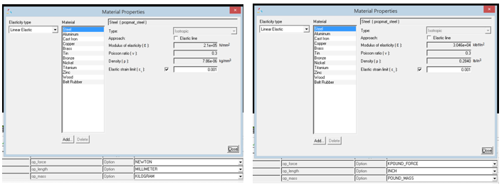
1.NLFE – the belt is modeled as an NLFE Body
2.Discretized rigid bodies –the belt is approximated to a series of rigid bodies connected via spring-damper forces

mv_14_120_03


Known limitations

NLFE Belt pulley currently can only be used where the belt-pulley plane is parallel to the Global XZ plane
Once the system is created, the belt modeling method cannot be toggled.
Discretized rigid bodies Belt pulley system consists of a large set of entities. Creating or working with this system could be slower


hmtoggle_arrow1Unit Support to Material Properties

MotionView now handles unit conversions automatically on Material Properties. The properties in the Materials dialog display the values in the Solver Units that are selected. Mass-inertia & CG properties of rigid bodies that get their properties from primitive graphics or CADGraphics and NLFE Body get updated automatically when units are changed.

mv_14_120_01


hmtoggle_arrow1Ellipsoid Graphics Support

It is now possible to define an ellipsoid graphics in MotionView that can be used with MotionSolve and Adams.

mv_14_120_02


hmtoggle_arrow1Resolved Issues
An app error with the expression builder when an entry field contains improper function is fixed.
An application crash associated with the usage of curly braces in the location function loc_along_dir has been fixed.
An issue with resolving point for orientation of tire graphics has been resolved.
Mass-Inertia of CADGraphics (and thereby their parent body mass-inertia) were not being updated immediately when property of materials referenced by CADGraphics were changed. This issue has been fixed.
An issue with components of inactive File Graphics not being read when they are activated is resolved.
While importing CAD, MotionView now uses the underscore (_) that might exist in the component names while assigning a varname.
An issue with the macro “Export MDL” in HyperMesh to generate an h3d has been resolved.
A regression in v14.0.110 in the 3D Cartesian Curve where the curve was being displayed by default in the Global Frame has been resolved.
An issue with CG inertia summary where the dialog closes when using the Return key after an entry has been fixed.
A crash while assigning material to a system attachment is resolved.
The MNF to H3D conversion in flexprep has been enhanced to calculate inertia invariants for MotionSolve. MotionView will now show FEM Inertia Properites for the flexible body with the newly converted h3d from mnf.
A minor enhancement to the Assembly Wizard GUI now provides the ability to skip the Attachment Wizard after selection of systems.