This section documents other important enhancements that have been made to MotionView.
Geometric Stiffening for CMS Flexible Bodies
You can model geometric stiffening for CMS flexible bodies in MotionSolve. Geometric or stress stiffening is an effect most commonly seen in beams under tension where the frequency of the fundamental modes increases as the tension is increased. Such an effect can be observed in rotating beam structures like helicopter or wind turbine rotor-blades.
Include the stress stiffness data in your CMS flexible body by including the following in your FEM file:
CMSMETH, 1, CBG, , 15
CBG is the keyword that instructs OptiStruct to create the CMS flexible body with additional geometric stiffness data.
You can then import this flexible body in your MotionView model as you would ordinarily. Note: Only the Craig-Brampton method is currently supported for calculating the geometric stiffness data.
This new MotionSolve capability is completely supported in MotionView also.
A GUI option is available to specify geometric stiffness.
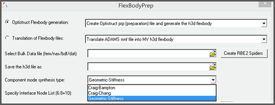
Selecting the highlighted option would include the relevant CMSMETH statement of the form CMSMETH, 1, CBG, , 15 into the FEM File.
|
“Include geometric stiffening” checkbox is now available in the Flex-body panel. This option will only be activated when the flex h3d contains the geometric stiff (GEOSTIFF) data that is saved while generating the flexible body during the CMS process.
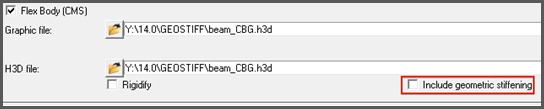
Checking on this option will enable export of the geometric stiffness data into MotionSolve XML file.
|
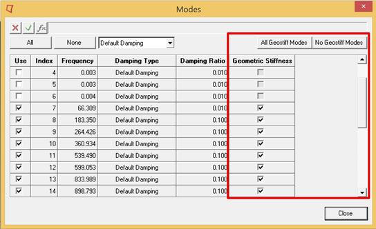
The “Modes” dialog in the flex-body panel now contains an additional column to control export of geometric stiffness data for each mode.
Turning off geometric stiffness data for certain modes can significantly improve the solution time. However, you should be sure that the modes that are turned off have a minor influence on geometric stiffening effects.
|
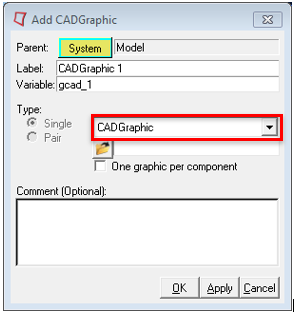
In this release, MotionView introduces new functionalities based on the Parasolid geometry engine. A new ability to import geometry of type “CADGraphic” is now available. All common formats can be imported.
You will experience several benefits because of this capability.
| • | All common CAD file formats are supported and can be easily imported as graphic statements |
| • | CAD Geometry imported in this way has mass and inertia attributes |
| • | The Body to which CADGraphics are attached, can automatically inherit the mass and inertia properties based on the geometry properties |
| • | User can pick specific components in geometry and export them to solver. A separate parasolid file will be generated with the component being selected. No mesh data written to XML file. |
| • | User has the flexibility to change mesh refinement level of geometry by adjusting the fidelity factor before exporting to MotionSolve. |
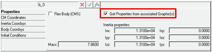
The underlying Parasolid geometry engine is also used to automatically compute mass and inertia properties for simple analytical shapes such as spheres, cylinders, boxes and frusta.
An option is provided in body panel using which user may choose to inherit mass and inertia properties from associated graphics.
|
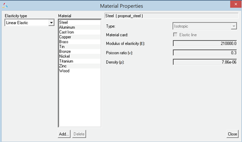
A default set of materials with material properties is now available. These materials can be used either in an NLFE Body or CADGraphics. The Materials can be accessed using the menu Model > Materials.
|
| • | Multiple picking from Graphics area to cut/delete entities. Hold Shift key to select many entities. |
| • | Merging multiple bodies from the graphics area. User can select two or more bodies (using the Shift key), use the right click to merge the bodies to a new body or to Ground Body |
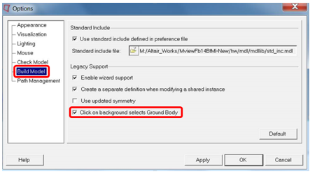
| • | A new option is now available in MotionView to select a Ground Body.When Body collector is active (to pick a body as a reference into an entity panel), clicking on empty space in the Graphics area picks Ground Body with following option ON. |
|
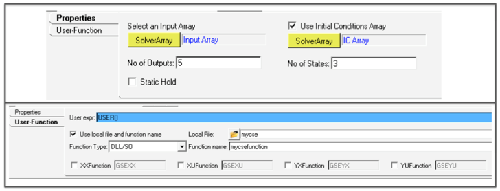
The General State Element, also known as CONTROL_STATEEQN in MotionSolve, is now fully supported. This includes the user interface and complete MDL support. You no longer need a Templex template to use this capability. A Control_StateEquation icon is available in the “Control Entity” toolbar to add the entity.
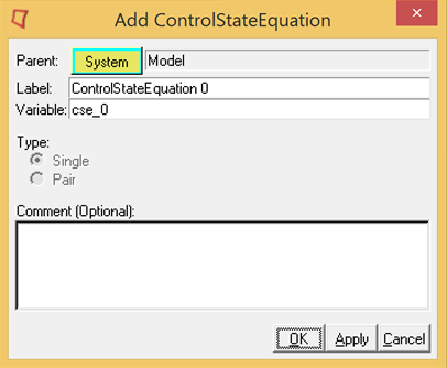
The two tabs in the panel can be used to define all the necessary inputs to the control state equation.
|
This enhancement is applicable only in the MotionSolve mode. Traditionally, the REFERENCE_VARIABLE in MotionSolve has explicitly defined a new algebraic variable through an expression or a user-subroutine. Solver Variables are now extended so that they are implicitly defined. This means that VARIABLES can now be used to define constraints, and the VARIABLE, instead of assuming the value of the expression, now becomes the Lagrange Multiplier required to enforce the constraint.
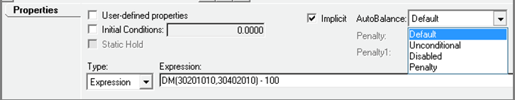
The SolverVariable panel along with the implicit option has additional controls to tell MotionSolve how the Lagrange Multiplier has to be handled.
|
MotionView now supports adding a modal force on a flexible body (Force_FlexModal in MotionSolve). A modal force can be a distributed force such as fluid pressure or aerodynamic load that can vary with regards to time.
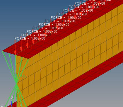
The distributed force should be applied on the FE model that would be used to generate the CMS flexible body. The force would be decomposed into modal form.
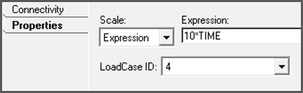
MotionView presents the modal force as load case ID as available in the flexible body H3D. The modal force can be scaled during simulation if needed.
|
MotionView now supports a Scalar action only force or torque. This means that Action Only forces or torques can be applied in a direction specified by the z-axis of a Marker.
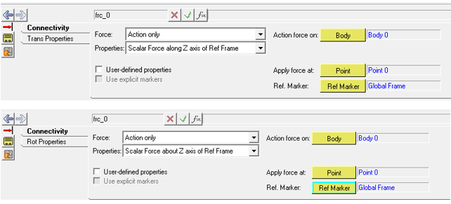
|
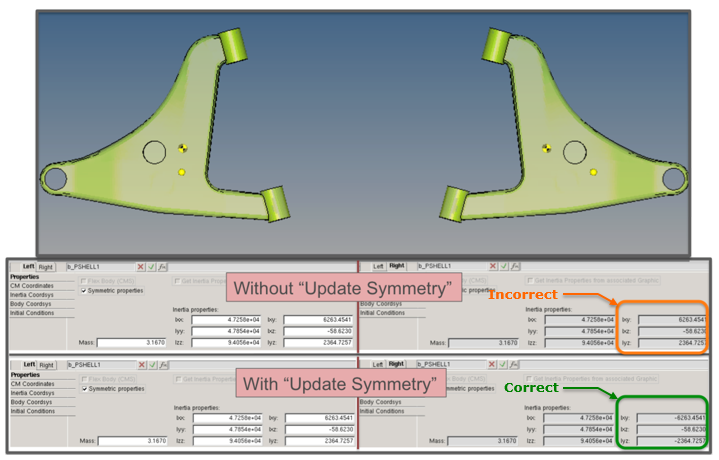
A new symmetry option is now available in MotionView to define symmetric body pairs. Cross products of inertias are properly negated (about the Global ZX plane) when a body is reflected. This new option can be turned on using the Tools > Options > Build Model. The symmetric pair’s properties correspond to the bodies being represented as mirror reflections of each other.
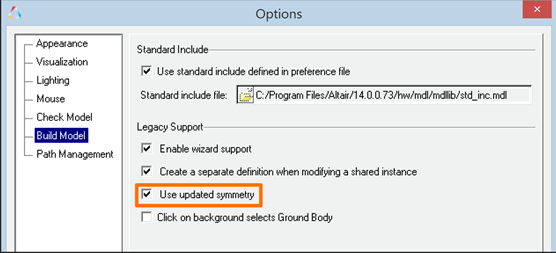
The new calculation considers the offset between the CM marker and IM marker if any. Non-symmetry of the CM location is not considered. Also, the symmetry is not applied to initial conditions.
|
The option “Body Deformable” that is used to define a flexible body has been renamed to “Flex Body (CMS)” to distinguish it from the NLFE body. (The NLFE Body is added through the “Add Body” dialog)
The “Flex Body CMS” panel has additional options:
| • | Rigidify – to set the MotionSolve attribute rigidified = “true” in <Body_Flexible |
| • | Include Geometric stiffening – To include geometric stiffening during solution of flexible body whose H3d has geometric stiffness data |
|
| • | Now opens with mesh options expanded |
| • | Graphic H3d files are automatically populated while selecting an input file |
| • | Multiple confirmation messages related to successful import are eliminated. |
|
MotionView now provides a new TCL API, GetAggregateCGAndInertia, which allows you to calculate the aggregate mass, center of gravity, moment of inertia and product of inertias for multiple systems or multiple bodies in your model. Documentation for this function is included with this release.
|
MotionView now supports translation of .plt to RPC format.
|
The File menu now lists the four most recent MDL files used.
|


