MotionSolve is a state-of-the-art multi-body solver available in HyperWorks. It has a complete set of modeling elements and powerful numerical methods to support a full set of analysis methods. The accuracy, speed and robustness of MotionSolve have been validated through extensive testing with customer models and test data. MotionSolve also offers unmatched compatibility with ADAMS/Solver input.
In version 14.0, MotionSolve had the following major highlights:
| • | Revamped 3D rigid body contact solution that improves robustness, accuracy and performance |
| • | Non-linear finite element bodies are introduced in MotionSolve |
| • | Geometric stiffening support is added for linear flexible bodies |
| • | A new Python Lexicon is available for model building |
| • | Several enhancements to Linear Analysis |
In this version of 14.0.110/210, which is a service update to the 14.0 release, MotionSolve brings continuous improvements to the major functionalities.
MotionView comes with an improved graphical rendering engine that offers smoother rendering of geometrical objects and a better visual appearance.
MotionView now provides the ability to use geometrical features such as edge and surfaces while creating entities. Through this feature, an edge or a surface of CADGraphics and primitive graphics such as Box and Cylinder can be used to pick origin or alignment axis for entities such as joints, bushings and forces. A point or a vector entity would be automatically created and resolved into the Entity panel.
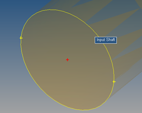
Point at circle center
|
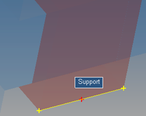
Point at edge center
|
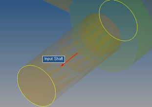
Vector at axis of cylindrical surface
|
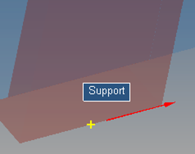
Vector on edge
|
While picking the point/vector, hover the mouse on the edge/surface to highlight it. While picking a point, a red cr
oss mark + indicates the location of the point being created if clicked. Yellow cross marks + indicate other potential location on the edge.
To use this feature, the option “Use CAD feature recognition for picking” needs to be turned on through Tools > Option > Build Model.
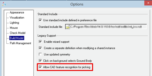
In addition, this option enables:
| - | Highlighting of graphics in the graphics area under mouse cursor relevant for selection of entities |
| - | Dim non-relevant entities during selection |
|
MotionSolve 14.0 introduced the “NLFE Body” as an experimental feature, which allows you to model non-linearly flexible beams and cables in your multi-body system. The NLFE Body is based on the Absolute Nodal Coordinate Formulation (ANCF). Nonlinearity can occur for two main reasons: (A) Geometric nonlinearity and (B) Material non-linearity. The NLFE body supports both. MotionView also introduced NLFE subsystems to model stabilizer bar and a helical spring system.
This release includes a more robust functionality for the NLFE in MotionSolve. The following improvements have been implemented for this release:
| • | You can now specify the maximum allowable von Mises strain for your NLFE component in the model. This is done by specifying a non-zero value for the attribute “Yield Strain” (YS) in the NLFE material card that can be set in MotionView using the Materials dialog. |
If the maximum von Mises strain in any element of the NLFE component exceeds this value during the simulation, MotionSolve will issue a warning message. MotionSolve monitors the maximum von Mises strain in the NLFE component for BEAM12, BEAMC and CABLE element types for transient and quasi-static analyses.
Specifying the maximum yield strain is helpful for the following scenarios:
| - | You want to control the maximum allowable strain in your component |
| - | You want to keep the deformation in your component within elastic range and know beforehand the elastic yield strain for the material you are modeling |
| - | As a debugging tool when the simulation fails due to excessive deformation in your NLFE component |
| • | Several fixes have been made to enhance the robustness of displacement and stress calculations for BEAM elements subjected to different kinds of loading (axial, bending and torsion) during static, quasi-static and transient analyses. |
| • | MotionView now allows you to define a global method of attaching a marker to an NLFE body for defining joints, forces, bushes etc. This is achieved by defining an environment variable HW_NLFE_CONN_TYPE. You may specify up to six characters that determine how the additional 6 degrees of freedom at the NLFE attachment grid are to be constrained. For example: |
| - | HW_NLFE_CONN_TYPE = TTTTTT implies that the marker is fully clamped to the grid. The grid cannot be subjected to any axial or shear strain. This is the recommended value. |
| - | HW_NLFE_CONN_TYPE = FFFTTT implies that the marker is partially clamped to the grid. The grid can only undergo axial deformations but no shear deformation. |
| - | HW_NLFE_CONN_TYPE = TTTFFF implies that the marker is partially clamped to the grid. The grid can only undergo shear deformations but no axial deformation. |
| - | HW_NLFE_CONN_TYPE = FFFFFF implies that the marker is not clamped to the grid. All deformations are allowed on the grid. |
| - | For more details, please see the documentation on CONN0 in the solver reference manual. |
| • | Issues related to calculations of CG and Inertia for different beam cross sections have been addressed. |
| • | The ROD and TUBE sizes were wrongly displayed in MotionView graphics area. This issue has been resolved. |
| • | A crash issue when invalid values are specified for no. of segments for ROD and TUBE sections is resolved. |
| • | MotionView now can identify the correct GRID that needs to be used when an entity attached to the NLFE body at that location uses a coincident point not part of NLFE connectivity. |
| • | An option to insert/delete a point between 2 existing connectivity points is now available. |
| • | Creating displacement/velocity/acceleration outputs on NLFE body is available. MotionView attempts to measure output at the CG location of the body. If a connecting point at CG is not available, the output at a location closest to the CG is created. |
|
| • | The Automated report available for a contact simulation is updated. |
| - | The animation of forces page appears before the Contact Overview page |
| - | The issue of end time setting to 1 s irrespective of the simulation time is resolved |
| - | The force animation shows region output instead of force on each element |
|
A new air spring model is available as an Auto Entity in MotionView. The air spring force is interpolated from a table of force verses spring height and static inflation pressure, which is typically published by spring manufacturers. You enter the spring trim load and trim height and MotionSolve calculates the static inflation pressure automatically. You may include a bumpstop with the air spring as well. The air spring and bumpstop force properties are read from TeimOrbit format property files.
To add an air spring to your MotionView model:
| • | Load the Vehicle Dynamics Tools preference file by picking Load > Preference File from the File menu in MotionView and then selecting the MBD Vehicle Dynamics Tools preference file. |
| • | Right click on the model in the browser and from the context menu pick “Add Auto Entity” to launch the Add Entity dialog. |
| • | In option menu on the Add Entity dialog pick “AutoAirSpring”, select single or pair, and click OK. |
|
The Full Vehicle Kinematics and Compliance Event available via the task wizard in MotionView is now documented in the online help under the topic
MotionView > Vehicle Dynamics Modeling > MDL Library User's Guide > Vehicle Modeling Library User's Guide > Events.
|
The Auto Entities for MF-TYRE/MF-SWIFT, FTIRE/HTIRE, and CDTire now support offsetting the wheel/tire CM along the spin axis. A positive offset moves the CM outboard from the vehicle X-Z-plane. In addition you can offset the wheel hub graphics as well.
|
COSIN FTire shipped with MotionSolve 14.0.210 is updated to version 2016-1. However, in the future releases of MotionSolve, FTire binaries will not be included. Altair recommends obtaining FTire from COSIN and installing FTire independently of MotionSolve. When you run FTire with MotionSolve, the COSIN initialization file (e.g. cosin_2016-1.ini) is read to identify the FTire installation, so you can be assured that the latest installed version of FTire is used.
Note: Using FTire 2016-1 with MotionSolve 14.0.210 requires a COSIN initialization file in your home directory.
|
| • | It is now possible to fit the screen display using the keyboard shortcut “f” |
| • | MV-HST – The Import Model Parameters dialog now shows only the active systems and analyses |
| • | MV-HST – An issue with active analysis not being selected by default has been resolved |
| • | User defined properties are now available for Plant Input and Plant Output solver array |
| • | Template of type USER & ADAMS can be evaluated prior to all other entities using the MDL *Set statement. For e.g. *Set(varname.pre_evaluate, true) where varname is the variable name of the template entity |
|
Resolved Issues in MotionView
Previously, the powertrain CSE function names were not mapped correctly from the ADM/ACF deck to the MotionSolve XML file. With this release, the following names are mapped automatically:
ADM function name
|
XML function name
|
GSEXU977
|
GSEXU
|
GSEYX977
|
GSEYX
|
GSEYU977
|
GSEYU
|
Note: The function name GSEXX977 was being mapped correctly to GSEXX in version 14.0.
|
| • | Previously, transfer functions calculated from the A, B, C and D matrices of a model containing a SISO modelling element did not match the transfer function calculated by performing an FFT on the transient results. These two are expected to be the same. This has been identified as a bug and has been fixed with the current release. |
| • | With the previous release, the transfer function calculated between acceleration and force (ACC/F) did not match with the same transfer function calculated in Brand-X. This was identified to be due to the D matrix being calculated incorrectly. This has been fixed with the current release. |
| • | A number of changes have been made to the energy distribution tables that are calculated and written to the screen and results file by MotionSolve. These are listed below: |
| - | The rotational spring damper (RSPDP) element is now included in the energy distribution tables. |
| - | The linear spring damper (SPDP) element displayed entries only in the “X” column of the energy tables. This has been fixed. |
| - | For certain elements, the sum of KE/SE/DE energy in individual directions did not sum up to the value displayed under the total energy column. This has been fixed. |
| - | In certain cases, the total kinetic energy (KE) may be very small (O(10-12)). This small numerical value results in MotionSolve reporting zero kinetic energy (KE) distribution. To avoid this situation, the normalization scheme for the eigenvectors has been modified. Owing to this change, you should expect the total kinetic energy (KE) values to be different whereas the distribution remains the same. |
| - | For a force element (scalar or vector), if the force expression was explicitly defined to be zero in the model, MotionSolve did not write out the corresponding strain and dissipative energy distributions for this element (as they will be zero). With this release, MotionSolve does not exclude such elements from the energy distribution tables. |
| • | In MotionSolve 14.0, the kinetic and strain energy distributions do not match between equivalent model elements (like Force_Bushing and Force_Vector_Twobody, Force_SpringDamper and Force_Scalar_TwoBody) for certain modes in the linear analysis. This has been fixed with the current release. |
| • | Previously, the use of VARVAL while requesting ABCD matrices after a linear analysis yielded incorrect results. This has been fixed within this release. |
|
Previously, the RESTART action caused the solver to restart whenever the sensor criteria is true. This can potentially cause an endless restart if the sensor criteria remains true after the solver restarts. This behavior has been modified such that the solver restarts only when the sensor criteria changes from false to true, thus avoiding the possibility of an endless solver restart.
|
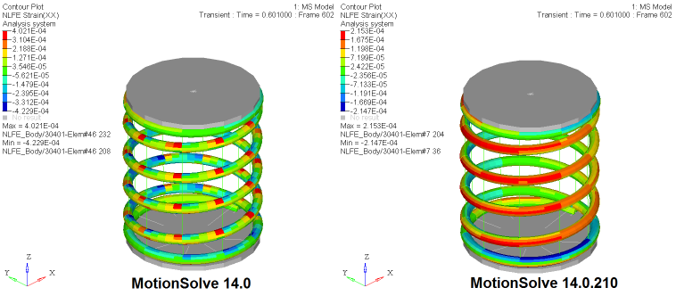
Previously, the strains/stresses reported by MotionSolve for the helical spring created by the MotionView subsystem were discontinuous. This has been fixed starting with the current release.
|
Other Enhancements for MotionSolve
With this release, support for a number of USERSUBs has been added to a number of Lexicon statements such as ARYSUB (ARRAY), STRING_READ (STRING), GRASUB (GRAPHICS), MATRIX_READ (MATRIX), etc.
|
This release introduces support for modal displacement, velocity and acceleration as MotionSolve expressions as well within the data access subroutines SYSFNC and SYSARY.
MotionSolve expression
|
Description
|
Q(f_id, m_id)
|
Modal displacement based on flexbody id f_id and mode id m_id
|
QDOT(f_id, m_id)
|
Modal velocity based on flexbody id f_id and mode id m_id
|
QDDOT(f_id, m_id)
|
Modal acceleration based on flexbody id f_id and mode id m_id
|
SYSFNC subroutine
|
Description
|
c_sysfnc(“Q”,…)
|
Returns modal displacement based on flexbody id and mode id specified in ipar
|
c_sysfnc(“QDOT”,…)
|
Returns modal velocity based on flexbody id and mode id specified in ipar
|
c_sysfnc(“QDDOT”,…)
|
Returns modal acceleration based on flexbody id and mode id specified in ipar
|
SYSARY subroutine
|
Description
|
c_sysary(“Q”,…)
|
Returns modal displacement based on flexbody id and mode id specified in ipar
|
c_sysary(“QDOT”,…)
|
Returns modal velocity based on flexbody id and mode id specified in ipar
|
c_sysary(“QDDOT”,…)
|
Returns modal acceleration based on flexbody id and mode id specified in ipar
|
Note: The support for SYSFNC and SYSARY is also available for the Python version of the subroutine. For more details on usage and syntax, please refer to the reference manual.
|
This release adds support for the PRINT action in the Sensor model statement. When the PRINT action is triggered, MotionSolve writes an additional output to the results files at the time the action is triggered.
|
The MFOSUB can now be defined as a Python script in addition to being defined as a FORTRAN/C/C++ compiled user subroutine.
|
MotionSolve will now check if the beam length, Young’s Modulus and/or Shear Modulus are specified as non-positive numbers (which is unrealistic) and will report an error and halt the simulation if these conditions are detected.
|


