MotionSolve
MotionSolve is a state-of-the-art multi-body solver available in HyperWorks. It has a complete set of modeling elements and powerful numerical methods to support a full set of analysis methods. The accuracy, speed and robustness of MotionSolve have been validated through extensive testing with customer models and test data. MotionSolve also offers unmatched compatibility with ADAMS/Solver input.
In version 14.0, MotionSolve had the following major highlights:
| • | Revamped 3D rigid body contact solution that improves robustness, accuracy and performance |
| • | Non-linear finite element bodies are introduced in MotionSolve |
| • | Geometric stiffening support is added for linear flexible bodies |
| • | A new Python Lexicon is available for model building |
| • | Several enhancements to Linear Analysis |
In this version of 14.0.120/220, which is a service update to the 14.0 release, MotionSolve brings continuous improvements to the major functionalities
In version 14.0 the “NLFE Body” which allows you to model non-linearly flexible components in your multi-body system was introduced as an experimental feature. This version of 14.0.120 & 14.0.220 marks the formal release of the NLFE.
A generic NLFE Body can be created using either the BEAM or CABLE element. The NLFE Body is based on the Absolute Nodal Coordinate Formulation (ANCF). Nonlinearity can occur for two main reasons: (A) Geometric nonlinearity and (B) Material non-linearity. The NLFE body supports both.
Refer to MotionView User Guide and MotionSolve Reference Guide for more details.
This release includes a more robust functionality for the NLFE in MotionSolve. The following improvements have been implemented for this release:
| • | In MotionSolve 14.0.210, you could specify the maximum allowable von Mises strain for your NLFE component in the model. |
If the maximum von Mises strain in any element of the NLFE component exceeded this value during the simulation, MotionSolve would issue a warning message. This message has been improved – the Body_Flexible ID for which the violation occurs is now included within the message for easy identification and debugging.
The following is an example of this updated warning message:
WARNING: Maximum vonMises strain exceeded maximum strain (YS) specified for NLFE element BEAM12 (id=20000000) on Body_Flexible (id=30105) at time=1.003E+00
Maximum strain Computed : 1.027E-03
Maximum strain Specified: 1.000E-03
Future warning for yield strain violation suppressed
| • | Several fixes have been made to enhance the robustness of displacement and stress calculations for BEAM elements subjected to different kinds of loading (axial, bending and torsion) during static, quasi-static and transient analyses. |
| • | MotionView now supports providing number of fibres information for Cable elements. |
| • | An additional set of constraints CONN0 are introduced by default by MotionView at NLFE grids that are associated with markers to rigidify the grid. The constraints are of the form <CONN0 id = “conn_id” gid = “grid_id” conn = “TTTTTT” />. The statement constrains the gradient vector. First 3 keywords in the conn attribute represent constraint on the gradients along X, Y & Z direction while the remaining 3 represent constraint in the rotational (shear) direction. The form of these constraints can be changed using an environment variable HW_NLFE_CONN_TYPE = ssssss, where s can be either ‘T’ or ‘F’. To modify or disable the default constraint, define the environment variable HW_NLFE_CONN_TYPE with the required CONN0 string. You may specify up to six characters that determine how the additional 6 degrees of freedom at the NLFE attachment grid are to be constrained. For example: |
| - | HW_NLFE_CONN_TYPE = TTTTTT implies that the marker is fully clamped to the grid. The grid cannot be subjected to any axial or shear strain. This is the default value. |
| - | HW_NLFE_CONN_TYPE = FFFTTT implies that the marker is partially clamped to the grid. The grid can only undergo axial deformations but no shear deformation. |
| - | HW_NLFE_CONN_TYPE = TTTFFF implies that the marker is partially clamped to the grid. The grid can only undergo shear deformations but no axial deformation. |
| - | HW_NLFE_CONN_TYPE = FFFFFF implies that the marker is not clamped to the grid. All deformations are allowed on the grid. |
| - | For more details, please see the documentation on CONN0 in the solver reference manual. |
|
With this release, MotionSolve introduces a co-simulation interface with solidThinking Activate. Activate is a modern block diagram environment to design and improve multi-disciplinary systems. Activate not only supports co-simulation with MotionSolve, but also supports the Functional Mockup Interface (FMI), both for model exchange and co-simulation.
This interface lets you simulate complex systems that include a multibody system with one or more control subsystems.
|
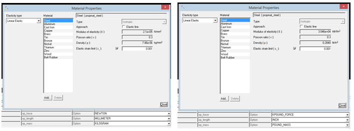
MotionView now handles unit conversions automatically on Material Properties. The properties in the Materials dialog display the values in the Solver Units that are selected. Mass-inertia & CG properties of rigid bodies that get their properties from primitive graphics or CADGraphics and NLFE Body get updated automatically when units are changed.
|
Version 14.0 introduced “NLFE Subsystems” in an experimental form along with the NLFE body. The NLFE Subsystem contain tools to create an NLFE based stabilizer bar and helical spring. In this version, the toolbar “NLFE Subsystems” has been renamed as “Subsystems”. Along with NLFE, the experimental tag on the Subsystems is also removed. In addition, a belt pulley system creation tool is made available.
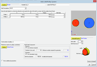
Belt Pulley System
A belt-pulley system can now be assembled quickly using the Belt-Pulley Subsystem tool available within the Subsystems toolbar.
Two types of belt modeling methods are now available.
| 1. | NLFE – the belt is modeled as an NLFE Body |
| 2. | Discretized rigid bodies –the belt is approximated to a series of rigid bodies connected via spring-damper forces |
Known Limitations
| • | NLFE Belt pulley currently can only be used where the belt-pulley plane is parallel to the global XZ plane. |
| • | Once the system is created, the belt modeling method cannot be toggled. |
| • | Discretized rigid bodies Belt pulley system consists of a large set of entities. Creating or working with this system could be slower. |
|
With this release, MotionSolve adds the following data access functions:
These allow you to query the model during the simulation and write out contact information in a format desired by you. This comes in handy when trying to export loads from contact to a finite element or fatigue solver. Using these newly added functions, you may write out a file to disk in a format desired by your downstream CAE tool. For syntax and usage, please refer to the reference manual.
|
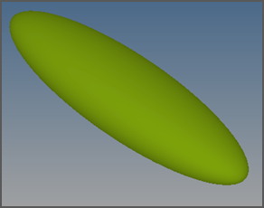
It is now possible to define an ellipsoid graphics in MotionView that can be used with MotionSolve.
|
Enhancements to the Python Lexicon
With this release, additional support for modelling entities has been added to the Python Lexicon
| • | The INTEGRATOR statement now supports the following parameters: |
| • | The H3DOUTPUT statement now supports the LINEAR_ANIM attribute |
| • | The LINEAR statement is now supported in the lexicon |
|
| • | An app error with the expression builder when an entry field contains improper function is fixed. |
| • | An application crash associated with the usage of curly braces in the location function loc_along_dir has been fixed. |
| • | An issue with resolving point for orientation of tire graphics has been resolved. |
| • | Mass-Inertia of CADGraphics (and thereby their parent body mass-inertia) were not being updated immediately when property of materials referenced by CADGraphics were changed. This issue has been fixed. |
| • | An issue with components of inactive File Graphics not being read when they are activated is resolved. |
| • | While importing CAD, MotionView now uses the underscore (_) that might exist in the component names while assigning a varname. |
| • | An issue with the macro “Export MDL” in Hypermesh to generate an h3d has been resolved. |
| • | A regression in v14.0.110 in the 3D Cartesian Curve where the curve was being displayed by default in the Global Frame has been resolved. |
| • | An issue with CG inertia summary where the dialog closes when using the Return key after an entry has been fixed. |
| • | A crash while assigning material to a system attachment is resolved. |
| • | The MNF to H3D conversion in flexprep has been enhanced to calculate inertia invariants for MotionSolve. MotionView will now show FEM Inertia Properites for the flexible body with the newly converted h3d from mnf. |
| • | A minor enhancement to the Assembly Wizard GUI now provides the ability to skip the Attachment Wizard after selection of systems. |
|
Translation of MFORCE from ADM to XML
| • | This release includes a fix to correctly translate the MFORCE/Force keyword from an ADM deck to the XML deck. |
Memory leaks in Python access functions
| • | With the previous release, there were memory leaks while using the Python based data/model access functions. This meant that the memory usage of MotionSolve was much higher than it should have been. |
| • | This has been corrected with this release for the following access functions: |
py_gtcmat
|
py_sysary
|
py_relpar
|
py_str2dblary
|
py_str2intary
|
py_modinf
|
py_get_post_states
|
py_getidlist
|
py_get_full_matrix_data
|
py_get_sparse_matrix_data
|
py_gtaray
|
py_gtunts
|
py_slsqp
|
|
|
MSDAEMON crash in IPC co-simulation mode
| • | Previously, the msdaemon module (required to run an IPC based co-simulation) would crash at the end of a co-simulation with Activate and Simulink or when the co-simulation was paused and started. This issue has been fixed with this release. |
Contact force magnitude is calculated incorrectly
| • | With the previous release, for some models, the contact force magnitude reported by using the expression CONTACT(..) was incorrect. This has been fixed with the current release. |
CONN0 on Cable NLFE elements leads to solver failure
| • | In the previous release (14.0.210), any marker attached to an NLFE component would be accompanied by a CONN0 element in the ANCF XML file, which ensured that the marker was rigidly attached to the node of the NLFE component. However, for a CABLE element, this CONN0 may lead to a failure in the simulation. This issue has been identified and fixed with this release. |
Mode function fix
| • | The MODE function has been fixed to return the correct number based on the analysis type in MotionSolve: |
MODE
|
Description
|
1
|
Kinematics
|
3
|
Initial Conditions
|
4
|
Dynamics
|
5
|
Statics
|
6
|
Quasi-statics
|
7
|
Linear analysis
|
|
MotionAuto Updates
The MotionAuto extensions to MotionView and MotionSolve are available via the MBD Vehicle Dynamics Tools preference file and include the new and updated features described below. NOTE: you must install both the 14.0.120 HyperWorks Desktop and the 14.0.220 HyperWorks Solvers updates to obtain the new and updated features.
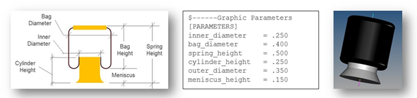
The autoAirSpring entity now sizes graphics based on parameters in the air spring property file. Within MotionView, users can update the graphics from the property file by pushing the update graphics button on the air spring panel. MotionSolve reads the air spring property file and creates properly sized graphics in the h3d output file. In addition the air-bag graphics have a toroidal top and bottom more representative of rolling lobe air spring graphics.
|
The Altair Advanced Driver is enhanced to support steering the vehicle from steering gear (e.g. rack-pinion or recirculating ball) without the need for a steering wheel and column. The vehicle parameters input to the driver now include markers on the left and right front wheels to enable the driver to determine the overall steering ratio.
|
The version of CDTire shipped with MotionSolve is updated to 4.2.3 from 4.1. CDTire version 4.2.3 includes:
CDTire/Realtime (CDT30/HPS)
The CDTire/Realtime model includes these new features:
| • | LDE (large deformation element): This extension has been added from CDTire/Legacy model 30. It implements tire ground out behavior. |
| • | PIN_FLAG/PREF: This extension has been added from CDTire/Legacy model 30. It implements inflation pressure dependent rigid body frequencies FTX, FTY and FRY. |
| • | CRY_RED_FLAG/_DEF/_RES: This extension has been added from CDTire/Legacy model 30. It implements deflection dependent reduction of CRY for large deformations. |
| • | PNEUMATIC_SCALE_TRAIL: This parameter scales the pneumatic trail to yield more accurate self-aligning torque. Default setting yields backward compatibility. |
| • | For more information, please refer to the CDTireUser Manual. |
CDTire/3D (CDT50)
The CDTire/3D model has these new features:
| • | TREAD_HEIGHT: The tread sensor height can now also be specified for each individual tread sensor ring. This allows modelling of rotationally symmetric tread gaps. |
| • | PIN_FLAG/PREF: This extension for SW_MODE=40 has been added from CDTire/Legacy model 40. It implements inflation pressure dependent rigid body frequencies FTX, FTY and FRY. |
| • | CRY_RED_FLAG/_DEF/_RES: This extension for SW_MODE=40has been added from CDTire/Legacy model 40. It implements deflection dependent reduction of CRY for large deformations. |
| • | For more information, please refer to the CDTireUser Manual. |
CDTire/MF++
CDTire version 4.2 introduces a new Magic Formula sub model called CDTire/MF+. The MF++ model estimates the contact patch shape, location and pressure distribution for coupling with CDTire/Thermal. To select CDTire/MF++ in ADAMS via GFORCE or ADAMS/Tire (CDT_MODEL_TYPE), set the model number to 10.
NOTE: CDTire v4.2.3 discontinues support for tire model 20 (CDT20). In addition road surface model 1000 (RSM1000) is no longer supported for use with tire model 30 (CDT30).
|
| • | Empty Wizard selection page displayed for 4 post analysis |
When using the MotionView Analysis Task Wizard to add a 4 post analysis to full vehicle model, an unneeded empty wizard page was displayed requiring users to push the “Next” one extra time. The empty page was removed.
| • | Road Tools fails to extract or plot centerline of CRG roads |
Given a road property file containing curved regular grid road data the road tool failed to extract or plot the road centerline giving an error instead. The issue is resolved.
| • | Models employing MF-TYRE/MF-SWIFT fail on RedHat Linux |
Model employing either MF-TYRE of MF-SWIFT tire models fail to run on computers running RedHat Linux with the message that shared object library TNO_DelftTyre.so could not be loaded because libgfortran.so is missing. The shared object library libgfortran.so is now packaged with MotionSolve eliminating the problem.
| • | Kinematic models fail when used with CDTire |
Kinematic models using CDTire failed because MotionSolve did not communicate to CDTire when successful solution steps occurred. Kinematic models using CDTire appeared to proceed in time, but as time advanced the simulation proceeded slower and slower until giving the appearance of a hung process.
For kinematic models MotionSolve now communicates successful solution steps CDTire and simulations proceed to completion.
|


