Title
Square plate torsion
|
|
Number
18.1
|
Brief Description
Torsion test on a cantilever plate submitted to two opposing forces on the same side.
|
Keywords
| • | Hourglass, mesh, and concentrated loads |
|
RADIOSS Options
| • | Boundary conditions (/BCS) |
| • | Element formulation (/PROP) |
|
Input File
4Q4: <install_directory>/demos/hwsolvers/radioss/18_Square_plate/Torsion/4Q4/.../TORSION*
8T3: <install_directory>/demos/hwsolvers/radioss/18_Square_plate/Torsion/8T3/.../TORSION*
8T3 inv: <install_directory>/demos/hwsolvers/radioss/18_Square_plate/Torsion/8T3_inv/.../TORSION*
2Q4-4T3: <install_directory>/demos/hwsolvers/radioss/18_Square_plate/Torsion/2Q4-4T3/.../TORSION*
|
Technical / Theoretical Level
Beginner
|
Overview
Physical Problem Description
This example concerns a torsion problem of an embedded plate subjected to two concentrated loads, as shown in the following diagram. This example illustrates the role of the different shell element formulations with regard to the mesh.
Units: mm, ms, g, N, MPa
The material used follows a linear elastic behavior with the following characteristics:
| • | Initial density: 7.8x10⁻³ g/mm3 |
| • | Young modulus: 210000 MPa |
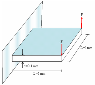
Fig 1: Geometry of the problem.
Analysis, Assumptions and Modeling Description
Modeling Methodology
Four different types of mesh are used:
| • | Mesh 1: two quadrilateral shells and four triangular shells (2Q4-4T3) |
| • | Mesh 2: four quadrilateral shells (4Q4) |
| • | Mesh 3: eight triangular shells (8T3) |
| • | Mesh 4: eight triangular shells (8T3 inverse) |
For each model, the following shell formulations are tested:
| • | QBAT formulation (Ishell =12) |
| • | QEPH formulation (Ishell =24) |
| • | Belytshcko & Tsay formulation (Ishell =1 or 3, hourglass control type 1, 3) |
| • | C0 and DKT18 formulations |
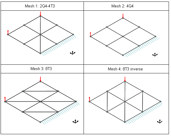
Fig 2: Square plate meshes.
RADIOSS Options Used
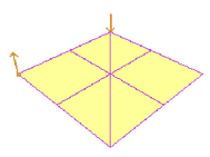
The boundary conditions are such that the three nodes of a single side and the two middle ones are blocked, while the others are free with respect to the Y axis.
Two concentrated loads are applied on the corner points of the opposite side. They increase over time as defined by the following function:
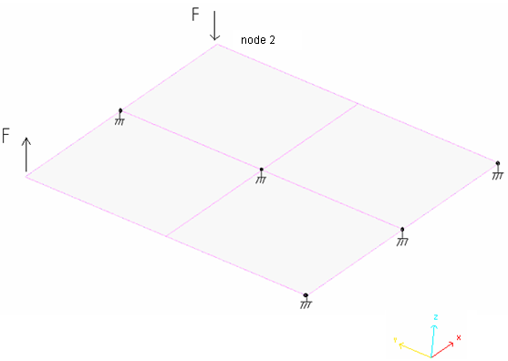
Fig 3: Boundary conditions and loads.
Simulation Results and Conclusions
Curves and Animations
This example compares several models concerning:
| • | the use of different element formulations for each mesh |
| • | the different types of mesh for a given element formulation |
Two criteria used to compare the results are:
| • | absorbed energy (internal and hourglass) |
| • | vertical displacement of the node under the loading point |
The following diagrams summarize the results obtained.
Energy Curves / Comparison for Element Formulations
Mesh 1: 2Q4-4T3
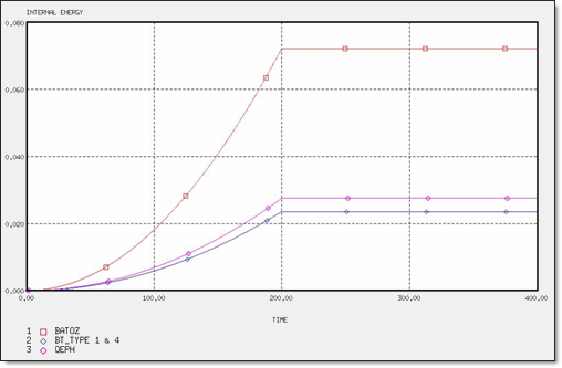
Fig 4: Internal energy for 2 x Q4 and 4 x T3 elements.
Mesh 2: 4Q4
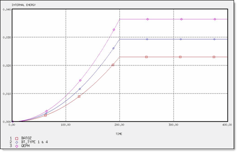
Fig 5: Internal energy for 4 x Q4 elements
Meshes 3 and 4: 8T3 and 8T3_INV
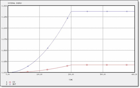
Fig 6: Internal energy for 8 x T3 elements.
Energy Curves / Comparison for Mesh Definitions
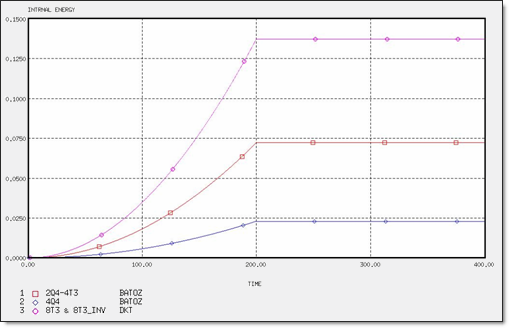
Fig 7: Internal energy for different meshes.
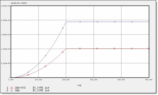
Fig 8: Hourglass energy for different meshes.
Displacement and Maximum Energy Comparison
|
2 Q4- 4 T3
|
4 Q4
|
8 T3
|
8 T3 Inverse
|
QEPH
|
BT_TYPE1
|
BT_TYPE4
|
BATOZ
|
QEPH
|
BT_TYPE1
|
BT_TYPE4
|
BATOZ
|
DKT
|
C0
|
DKT
|
C0
|
IEmax
|
2.74x10⁻²
|
2.35x10⁻²
|
2.37x10⁻²
|
7.21x10⁻²
|
3.64x10⁻²
|
2.93x10⁻²
|
2.97x10⁻²
|
2.30x10⁻²
|
1.37 x10⁻¹
|
1.69x10⁻²
|
1.37x10⁻¹
|
1.69x10⁻²
|
HEmax
|
---
|
1.01x10⁻⁴
|
1.03x10⁻⁴
|
---
|
---
|
1.94x10⁻⁴
|
1.98x10⁻⁶
|
---
|
---
|
---
|
---
|
---
|
DZmax
|
1.75x10⁻³
|
1.78x10⁻³
|
1.78x10⁻³
|
1.21x10⁻²
|
2.42x10⁻³
|
2.95x10⁻³
|
2.97x10⁻³
|
2.30x10⁻³
|
1.44x10⁻²
|
1.69x10⁻³
|
1.44x10⁻²
|
1.69x10⁻³
|
Conclusion
A square plate under torsion is a severe test to study the behavior of shell elements in torsion-bending. A general overview of the results obtained highlight the following key points:
| • | For the 4Q4 mesh, the results obtained using QBATOZ and QEPH are similar. BT elements are too flexible and are not significantly influenced by the hourglass formulation, due to the in-plane mesh. |
| • | For triangular meshes, the DKT element is able to bend much better, the co-element being too stiff. |
| • | The mesh with both Q4 and T3 elements may not comment like the other two, as one part uses the triangle elements employed in RADIOSS. |


