|
»Click here to display Table of Contents«
|

Body: Rigid |

|

|

|

|
|
Body: Rigid |
|
|

|

|
|
»Click here to display Table of Contents«
|
Body: Rigid |
|
|
|
|
|
Body: Rigid |
|
|
|
|
Model Element |
|||||||||||||||||||||||||||||||||||||||||||||||||||
Description |
|||||||||||||||||||||||||||||||||||||||||||||||||||
Body_Rigid defines a rigid body object in MotionSolve. This entity has mass and inertia properties. |
|||||||||||||||||||||||||||||||||||||||||||||||||||
Format |
|||||||||||||||||||||||||||||||||||||||||||||||||||
< Body_Rigid id = "integer" [ label = "string" ] cg_id = "integer" [ im_id = "integer" ] lprf_id = "integer" [ isground = { "TRUE"|"FALSE" } ]
mass = "real" [ inertia_xx = "real" inertia_yy = "real" inertia_zz = "real" inertia_xy = "real" inertia_yz = "real" inertia_xz = "real" ] [ v_ic_x = "real" v_ic_y = "real" v_ic_z = "real" w_ic_x = "real" w_ic_y = "real" w_ic_z = "real" v_ic_x_flag = {"TRUE"|"FALSE"} v_ic_y_flag = {"TRUE"|"FALSE"} v_ic_z_flag = {"TRUE"|"FALSE"} w_ic_x_flag = {"TRUE"|"FALSE"} w_ic_y_flag = {"TRUE"|"FALSE"} w_ic_z_flag = {"TRUE"|"FALSE"} vm_id = "integer" wm_id = "integer" ] [ is_wet_body = {"TRUE"|"FALSE"} cp_inp_id = "integer" ] /> |
|||||||||||||||||||||||||||||||||||||||||||||||||||
Attributes |
|
||||||||||||||||||||||||||||||||||||||||||||||||||
id |
Element identification number, (integer>0). This is a number that is unique among all Body_Rigid elements. |
||||||||||||||||||||||||||||||||||||||||||||||||||
label |
The name of the Body_Rigid element. |
||||||||||||||||||||||||||||||||||||||||||||||||||
cg_id |
Specifies the ID of the Reference_Marker that is located at the center-of-mass of the Body_Rigid, called the CG marker. |
||||||||||||||||||||||||||||||||||||||||||||||||||
im_id |
Defines a Reference_Marker that specifies the origin and the coordinate system in which the inertia matrix is specified. This marker is called the IM marker. im_id is optional. When not specified, it defaults to cg_id. |
||||||||||||||||||||||||||||||||||||||||||||||||||
lprf_id |
Optional attribute to specify the local part reference marker. This Marker is used as the coordinate system for all locations and orientations. |
||||||||||||||||||||||||||||||||||||||||||||||||||
isground |
Specifies whether the rigid body being defined is the Ground body or not. The value "TRUE" indicates that the rigid body that is being defined is the Ground body. The value "FALSE" indicates that the rigid body is not the Ground body. The attribute isground is optional. When not specified, it defaults to "FALSE". |
||||||||||||||||||||||||||||||||||||||||||||||||||
mass |
Specifies the mass of the Body_Rigid object. When specified, mass must be a positive number. The attribute mass is optional. If a rigid body is fully constrained and you are not interested in the constraint forces, then mass need not be specified. When omitted, zero mass is assumed. |
||||||||||||||||||||||||||||||||||||||||||||||||||
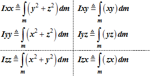
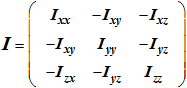
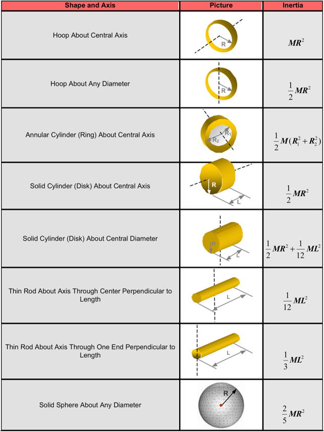
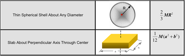
inertia_xx |
Define the moments of inertia and the products of inertia of the rigid body about the origin im_id and about its x-, y- and z-axes, respectively. See Comments 4-9 for more information about these quantities. The attributes inertia_xx, inertia_yy, inertia_zz, inertia_xy, inertia_yz and inertia_xz are optional. If a rigid body is fully constrained and one is not interested in the constraint forces, then these need not be specified. When specified: inertia_xx > 0 inertia_yy > 0 inertia_zz > 0 |
||||||||||||||||||||||||||||||||||||||||||||||||||
v_ic_x |
Specifies the initial translational velocities of the Body_Rigid CG Marker along the global x-axis. |
||||||||||||||||||||||||||||||||||||||||||||||||||
v_ic_y |
Specifies the initial translational velocities of the Body_Rigid CG Marker along the global y-axis. |
||||||||||||||||||||||||||||||||||||||||||||||||||
v_ic_z |
Specifies the initial translational velocities of the Body_Rigid CG Marker along the global z-axis. |
||||||||||||||||||||||||||||||||||||||||||||||||||
w_ic_x |
Specifies the initial rotational velocity about the X-axes of the Body_Rigid CG Marker. |
||||||||||||||||||||||||||||||||||||||||||||||||||
w_ic_y |
Specifies the initial rotational velocity about the Y-axes of the Body_Rigid CG Marker. |
||||||||||||||||||||||||||||||||||||||||||||||||||
w_ic_z |
Specifies the initial rotational velocity about the Z-axes of the Body_Rigid CG Marker. |
||||||||||||||||||||||||||||||||||||||||||||||||||
v_ic_x_flag |
A Boolean flag that indicates whether the x-velocity is known exactly or is just an initial guess. "TRUE" means this initial condition is applied exactly unless it is in conflict with a Motion input. "FALSE" means this initial condition is applied as an initial guess. It may be changed by MotionSolve to ensure that all constraints are satisfied. |
||||||||||||||||||||||||||||||||||||||||||||||||||
v_ic_y_flag |
A Boolean flag that indicates whether the y-velocity is known exactly or is just an initial guess. "TRUE" means this initial condition is applied exactly unless it is in conflict with a Motion input. "FALSE" means this initial condition is applied as an initial guess. It may be changed by MotionSolve to ensure that all constraints are satisfied. |
||||||||||||||||||||||||||||||||||||||||||||||||||
v_ic_z_flag |
A Boolean flag that indicates whether the z-velocity is known exactly or is just an initial guess. "FALSE" means this initial condition is applied as an initial guess. It may be changed by MotionSolve to ensure that all constraints are satisfied. |
||||||||||||||||||||||||||||||||||||||||||||||||||
w_ic_x_flag |
A Boolean flag that indicates whether the angular velocities along the x-axis are known exactly or is just an initial guess. |
||||||||||||||||||||||||||||||||||||||||||||||||||
w_ic_y_flag |
A Boolean flag that indicates whether the angular velocities along the y-axis are known exactly or is just an initial guess |
||||||||||||||||||||||||||||||||||||||||||||||||||
w_ic_z_flag |
A Boolean flag that indicates whether the angular velocities along the z-axis are known exactly or is just an initial guess |
||||||||||||||||||||||||||||||||||||||||||||||||||
vm_id |
Reference marker for translation initial velocities. |
||||||||||||||||||||||||||||||||||||||||||||||||||
wm_id |
Reference marker for angular initial velocities. |
||||||||||||||||||||||||||||||||||||||||||||||||||
is_wet_body |
A Boolean flag that determines whether this body will receive fluid loads from the corresponding fluid model while in co-simulation with AcuSolve. “TRUE” means that forces and torques computed in the AcuSolve simulation will be applied to the center of gravity of this body. “FALSE” means that forces and torques computed in the AcuSolve simulation will not be applied to this body. See Comment 18 for more details. |
||||||||||||||||||||||||||||||||||||||||||||||||||
cp_inp_id |
Specifies the ID of the Control_PlantInput element that holds the forces and torques computed in the AcuSolve simulation that will be applied to this rigid body. This attribute is only used when performing a co-simulation between MotionSolve and AcuSolve. See Comment 18 for more details. |
||||||||||||||||||||||||||||||||||||||||||||||||||
Comments |
|||||||||||||||||||||||||||||||||||||||||||||||||||
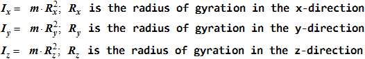
The radii of gyration contain information about the mass distribution in the rigid body. They are related to the physical dimensions of the rigid body.
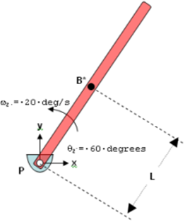
Note, initial velocities may also be specified using Jointlnitialvel_Trans, Jointlnitialvel_Trans and Jointlnitialvel_Cyl cards. Consider the simple pendulum shown below.
Assume that the pendulum body (shown in red) is pivoted at the global origin by a revolute joint, such that rotation is allowed about the global z-axis. The center-of-mass of the pendulum, B*, is at a distance L from the pivot P. The pendulum is initially defined such that its axis makes an angle of 60 degrees with the global x-axis and it rotates counterclockwise about the global z-axis at 20 degrees/second. For this configuration, the initial translational velocities of B* in the global coordinate system may be calculated as:
This system has one degree of freedom. Thus only one initial velocity may be specified. You have the option of specifying Vx, Vy or ωz. The revolute joint, which imposes the constraint Distance (PB*) = L, imposes the other velocities automatically using equations (1) and (2). Now consider the situation where you specify initial values for Vx, Vy and ωz. If the conditions (1) and (2) are not satisfied by the initial values you specify, MotionSolve changes Vx, Vy and/or ωz so that (1) and (2) are satisfied.
Note: If is_wet_body is specified as TRUE and the simulation is not coupled with AcuSolve, then MotionSolve ignores the is_wet_body and cp_inp_id attributes and their values. |
|||||||||||||||||||||||||||||||||||||||||||||||||||
Example |
|||||||||||||||||||||||||||||||||||||||||||||||||||
The first example below demonstrates the specification of the Ground body. <Body_Rigid id = "1" cg_id = "0" isground = "TRUE" /> The second example below demonstrates the specification of a "dummy body" that has zero mass and inertia properties. <Body_Rigid id = "2" cg_id = "21" isground = "FALSE" /> The third example demonstrates the specification of a body with mass but no inertia. They default to zero. Since no inertias have been specified, the modeling practice would require the body to be constrained in the angular directions. <Body_Rigid id = "2" cg_id = "21" im_id = "21" isground = "FALSE" mass = "1.0" v_ic_x = "0." v_ic_y = "0." v_ic_z = "0." v_ic_x_flag = "FALSE" v_ic_y_flag = "FALSE" v_ic_z_flag = "FALSE" /> The fourth example below demonstrates the complete specification of a rigid body that has both mass and inertia properties as well as initial translational and rotational velocities. <Body_Rigid id = "2" lprf_id = "1" cg_id = "21" im_id = "21" isground = "FALSE" mass = "1.0" inertia_xx = "0.0004892316" inertia_yy = "0.0004892316" inertia_zz = "0.0004892316" inertia_xy = "0." inertia_yz = "0." inertia_yz = "0." v_ic_x = "1.0" v_ic_y = "0." v_ic_z = "0." w_ic_x = "2.0" w_ic_y = "0." w_ic_z = "0." v_ic_x_flag = "FALSE" v_ic_y_flag = "FALSE" v_ic_z_flag = "FALSE" w_ic_flag = "FALSE" /> |
|||||||||||||||||||||||||||||||||||||||||||||||||||
Model Element |
|
Description |
|
PART defines a rigid body object in MotionSolve. This entity has mass and inertia properties. |
|
Declaration |
|
def PART(id, LABEL="", GROUND=False, MASS=0.0, CM=0, IM=0, IP=[], QG=[], REULER=[], ZG=[], XG=[], VX=0.0, VY=0.0, VZ=0.0, WX=0.0, WY=0.0, WZ=0.0, VM=0, WM=0, PLANAR=””, FUNCTION=””, ROUTINE=””, INTERPRETER=””, SCRIPT=””): |
|
Attributes |
|
id |
Element identification number (integer>0). This number is unique among all the PART elements. |
LABEL |
The name of the PART element. |
GROUND |
Specifies whether the PART being defined is the Ground PART or not. The value TRUE indicates that the PART that is being defined is the Ground PART. The value FALSE indicates that the PART is not the Ground PART. This attribute is an optional attribute. When not specified, it defaults to FALSE. |
MASS |
Specifies the mass of the PART object. When specified, mass must be a positive number. The attribute MASS is optional. If a PART is fully constrained and you are not interested in the constraint forces, then MASS need not to be specified. When omitted, a zero mass is assumed. |
CM |
Specifies the ID of the Marker that is located at the center-of-mass of the PART. |
IM
|
Specifies the ID of the Marker whose x,y,z coordinate system would be used to define the inertia matrix. This attribute is optional. When not specified, it defaults to CM. |
IP |
Specifies the mass moments of inertia and the products of inertia of the PART about the x,y,z axes of IM, either for the three main directions as [Ixx, Iyy, Izz] or additional for the sub-diagonal entries as [Ixx,Iyy,Izz,Ixy,Ixz,Iyz]. These attributes are to be specified in the following order: inertia_xx, inertia_yy, inertia_zz, inertia_xy, inertia_yz and inertia_zx. These attributes are optional. If a PART is fully constrained and you are not interested in the constraint forces, then these attributes need not be specified. However, when specified: Inertia_xx > 0 Inertia_yy > 0 Inertia_zz > 0 |
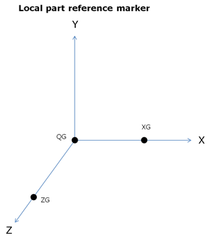
QG
|
Specifies the coordinates of local part reference marker. This Marker is used as the coordinate system for all locations and orientations. |
REULER
|
Specifies the Euler angles of local part reference marker with respect to the Global axes system. |
ZG
|
Specifies a point with respect to the Global reference frame, denoting the direction of z-axis of local part reference marker from QG. |
XG
|
Specifies a point with respect to the Global reference frame, denoting the direction of x-axis of local part reference marker from QG. |
VX |
Specifies the initial translational velocity of the PART along the VM x-axis. |
VY |
Specifies the initial translational velocity of the PART along the VM y-axis. |
VZ |
Specifies the initial translational velocity of the PART along the VM z-axis. |
WX |
Specifies the initial rotational velocity of the PART about the WM x-axis. |
WY |
Specifies the initial rotational velocity of the PART about the WM y-axis. |
WZ |
Specifies the initial rotational velocity of the PART about the WM z-axis. |
VM
|
Specifies the ID of the Marker whose axes system would be used to define the initial translational velocities of the PART (VX,VY,VZ). When not specified, it defaults to Global axes system. |
WM
|
Specifies the ID of the Marker whose axes system would be used to define the initial rotational velocities of the PART (WX,WY,WZ). When not specified, it defaults to CM axes system. |
PLANAR |
Specifies if this body is constrained to move in a plane. Choose from “XY”, “YZ” or “ZX”. Note MotionSolve interprets “XY” the same as “YX” and so on. |
FUNCTION
|
The list of parameters that are passed from the data file to the user defined subroutine. This attribute is common to all types of user subroutines and scripts. The name of the user subroutine depends on the type of the element. |
ROUTINE |
Specifies an alternative name for the user subroutine. |
INTERPRETER
|
Specifies the interpreted language that the user script is written in. Valid choices are MATLAB or PYTHON. |
SCRIPT |
Specifies the path and name of the user written script that contains the routine. |
CommentsSee Body_Rigid |
|
Example The first example below demonstrates the specification of the Ground body. PART(1,GROUND=True)
The second example below demonstrates the specification of a "dummy body" that has zero mass and inertia properties. PART(2,GROUND=False,CM=21)
The third example demonstrates the specification of a body with mass but no inertia. They default to zero. Since no inertias have been specified, the modeling practice would require the body to be constrained in the angular directions. PART(2,MASS=1,CM=21)
The fourth example below demonstrates the specification of rigid body with local part reference marker. PART(2,MASS=1,CM=21,QG=[10.000,0.000,0.000],ZG=[10.000, 0.000, 100.000],XG=[110.000, 0.000, 0.000])
The fifth example below demonstrates the complete specification of a rigid body that has both mass and inertia properties as well as initial translational and rotational velocities. PART(2,LABEL="Body 0",MASS=1,CM=21,IM=21,
|
|
The following MDL Model statements:
*SetBody() - asymmetric body pair
*SetBody() - symmetric body pair
*SetBodyIC() - all bodies in a system
*SetBodyICFlag() - single body
*SetBodyInertia() - asymmetric body pair