Block Format Keyword
/DRAPE – Define Fiber Orientation Change and Thinning for a Ply, due to draping
Description
This option is used to read fiber orientation changes and thinning for a ply which are usually the result a manufacturing process simulation.
The input is given by any number of lines.
Each line defines the angle change and the thinning for either a single element or a group.
Each element of the ply can only be called once for a single DRAPE option.
Format
(1)
|
(2)
|
(3)
|
(4)
|
(5)
|
(6)
|
(7)
|
(8)
|
(9)
|
(10)
|
/DRAPE/drape_ID
|
drape_title
|
Entity
|
Entity_ID
|
Thinning
|
θdrape
|
|
|
|
|
Field
|
Contents
|
SI Unit Example
|
drape_ID
|
Drape identifier
(Integer, maximum 10 digits)
|
|
drape_title
|
Drape title
(Character, maximum 100 characters)
|
|
Entity
|
Must be left justified.
(Integer)
SHELL: The entity is a 4 nodes shell element
SH3N: The entity is a 3 nodes shell element
GRSHEL: The entity is a group of 4 nodes shell element
GRSH3N: The entity is a group of 3 nodes shell element
|
|
Entity_ID
|
Entity identifier
(Integer)
|
|
Thinning
|
Ply thinning factor
(Real)
|
|
θdrape
|
Ply orientation change
(Real)
|
|
|
1. | The drape is used in /PLY and /PROP/PLY to take into account the manufacturing process on the ply orientation and thickness of the elements. |
2. | For each shell element, the ply first orthotropy direction is rotated by an angle θdrape in addition to the angles defined in the /PROP/PLY and /PLY or in the shell definition (depending of the value of flag def_orth in the ply input): |
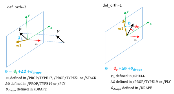
If def_orth = 2, the angle for between the reference direction and the first direction of orthotropy is:
Where, is defined in the /STACK or /PROP/STACK for ply layer i and is the angle of rotation of the layer with respect to the shell defined in the /PLY or /PROP/PLY option.
If def_orth = 1, the angle between the shell skew and the first direction of orthotropy is:
Where, is defined in the shell (/SHELL or /SH3N) and is the angle of rotation of the layer with respect to the shell, defined in the /PLY or /PROP/PLY option. See ply example in /PROP/TYPE17.
If def_orth =1, skew_ID, VX, VY, and VZ from the /PROP/TYPE17, /PROP/TYPE51 and /STACK input are ignored.
3. | The ply thickness ti of the element as defined in the ply is scaled using the ply thinning factor Thinning. |
|
See Also:
New Keywords in V2017
Material Compatibility