A tube made of two sheet metal pieces is intended to carry a load in both bending and torsion. The cross-section of the tube may be of any shape, but due to manufacturing requirements, it must remain constant through the entire length. Conventional shape optimization can be used to optimize the cross-section, but setting up the variables is time consuming. With topography optimization and pattern grouping, cross-section shape optimization can be performed in a fraction of the set up time. All optimization set up is done using the optimization panel and its subpanels in HyperMesh.
The loads and constraints are applied to the flanges at the ends of the tube, and are shown in Figure 1.1. Spot welds connect the two pieces of the tube along the flanges at regular intervals.
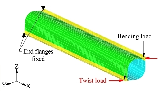
Figure 1.1: Loads and constraints for the spot welded tube.
The initial cross-section of the tube is arbitrarily chosen to be roughly circular. Two similar topography variables are defined to allow the shape of the tube to change. The two variables assign the blue and green pieces to be in the design domain while the flanges remain in their original shape. The topography variables are in the bulk data section using the DTPG card as shown below.
(1)
|
(2)
|
(3)
|
(4)
|
(5)
|
(6)
|
(7)
|
(8)
|
(9)
|
(10)
|
DTPG
|
1
|
PSHELL
|
1
|
|
|
|
|
|
|
+
|
2.5
|
85.0
|
NO
|
5.0
|
NORM
|
|
|
NONE
|
|
+
|
PATRN
|
1
|
0.0
|
0.0
|
0.0
|
1.0
|
0.0
|
0.0
|
|
The draw height of 5.0, combined with the upper and lower bounds of 2.0 and –2.0, allow a bead height of 10.0 model units in both directions (inward and outward) and a bead growth direction normal to the surface of the tube. A linear type pattern grouping is applied for this problem. This means that the beads formed during the topology optimization will be constant along a line parallel to the direction defined -- the central axis (X-axis) of the tube, in this case. By setting this pattern grouping option, the cross-section of the tube will be allowed to change, but will remain constant through the length of the tube.
The objective was set to minimize the weighted compliance of both load cases. In this case, both load cases were weighted equally. The mass of the tube was constrained to be below the initial value. OptiStruct generated the following solution for the model. See Figure 1.2.
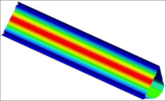
Figure 1.2: Optimized cross-section for the tube.
The solution is not completely smooth, but the basic shape of the tube is clear. The lower half of the tube has been lowered to increase the bending stiffness of the section while the upper half of the tube runs directly from one flange to the other to support the shear force generated by the twist load. The cross-sections of the model before and after optimization are shown in Figure 1.3.
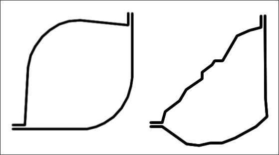
Figure 1.3: Cross-sections of the tube before and after optimization.
To verify the OptiStruct solution, a smooth model of the tube is built based upon the results. This model is shown in Figures 1.4 and 1.5. Static analysis shows the optimized cross-section after smoothing to have a 35% lower peak deflection for torsion and an 18% lower peak deflection for bending. Additionally, the mass of the part was reduced by 2.2%.
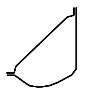
Figure 1.4: Smoothed cross-section of the tube.
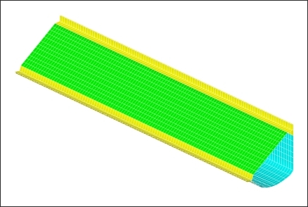
Figure 1.5: Finite element model of the smoothed optimized tube.
For the input file sample, see <install_directory>/demos/hwsolvers/optistruct/tube.fem.
See Also:
Manufacturability for Topography Optimization


