Finding a good reinforcement pattern for a single modal frequency is difficult when dealing with beaded plates since adding stiffness in one direction often reduces stiffness in another direction. The problem posed by finding a good reinforcement pattern for four modal frequencies simultaneously is more than four times more difficult. Add to that the difficulty constraints on the variety of reinforcement patterns, and the problem becomes a formidable task. By implementing topography optimization and pattern grouping, the task is greatly simplified and good quality results are quickly generated. All optimization set up is done using the optimization panel and its subpanels in HyperMesh.
The first four modal frequencies of a thin metal disc are to be optimized using bead reinforcement patterns. A variety of different manufacturing methods are being considered which place limitations on the bead reinforcement patterns allowed. The metal disc has a hole in the center where it is constrained (see Figure 2.1).
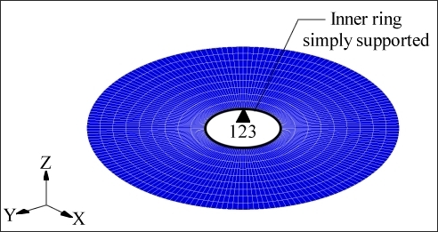
Figure 2.1: Constraints on the disc model.
The objective for the model is to increase the sum of the frequencies of the first four normal modes of the disc. This is achieved by using the WFREQ response type. The WFREQ response is the sum of the inverse eigenvalues of the chosen frequencies. This is done in order to assign higher weight to the earlier modes than the latter ones.
The first manufacturing method to be considered is turning the disc on a lathe. This restricts the bead reinforcements to being circular. A circular pattern grouping type is define. The DTPG card for this card is shown below.
(1)
|
(2)
|
(3)
|
(4)
|
(5)
|
(6)
|
(7)
|
(8)
|
(9)
|
(10)
|
DTPG
|
1
|
PSHELL
|
1
|
|
|
|
|
|
|
+
|
5.0
|
60.0
|
YES
|
2.5
|
NORM
|
|
|
SPC
|
|
+
|
PATRN
|
2
|
0.0
|
0.0
|
0.0
|
0.0
|
0.0
|
1.0
|
|
The anchor node is set at the center of the disc and the first vector points in the z direction. The nodes in the center ring are removed from the design region by choosing "Spc" in the "Boundary skip" option in the topography subpanel. No other additions to the finite element model were required.
The solution for the circular reinforcement pattern method is shown in Figure 2.2. OptiStruct generated a single wide circular bead running from the inner ring to about three-quarters of the way to the outer edge of the disc. The bead is gently sloped throughout its width. This reinforcement pattern more than doubled the frequencies of the first three modes and increased the fourth and fifth modes by over 75%.
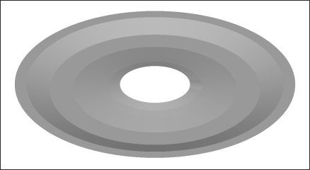
Figure 2.2: Solution for the circular bead pattern method.
The second manufacturing method to be considered is stamping with radial beads only. The topography set up for this approach is almost identical to that of the one for the circular approach with the only change being the radial pattern grouping type. The DTPG card for this configuration is shown below.
(1)
|
(2)
|
(3)
|
(4)
|
(5)
|
(6)
|
(7)
|
(8)
|
(9)
|
(10)
|
DTPG
|
1
|
PSHELL
|
1
|
|
|
|
|
|
|
+
|
5.0
|
60.0
|
YES
|
2.5
|
NORM
|
|
|
SPC
|
|
+
|
PATRN
|
4
|
0.0
|
0.0
|
0.0
|
0.0
|
0.0
|
1.0
|
|
The solution for the radial reinforcement pattern is shown in Figure 2.3. OptiStruct generated a series of eight evenly spaced wide radial beads. Note that the beads are not drawn to their full height. This demonstrates that full height beads are not necessarily optimal. This reinforcement pattern also doubled the frequencies of the first three modes and increased the fourth and fifth frequencies by more than 70%, but was not quite as efficient as the circular pattern.
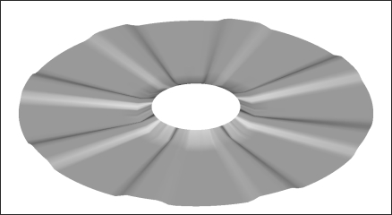
Figure 2.3: Solution for the radial bead pattern method.
The third manufacturing method to be considered was stamping with no constraints on the bead shapes. No pattern grouping was defined for this approach. The DTPG card for this set up is shown below.
(1)
|
(2)
|
(3)
|
(4)
|
(5)
|
(6)
|
(7)
|
(8)
|
(9)
|
(10)
|
DTPG
|
1
|
PSHELL
|
1
|
|
|
|
|
|
|
+
|
5.0
|
60.0
|
YES
|
2.5
|
NORM
|
|
|
SPC
|
|
The solution for this setting is shown in Figure 2.4. OptiStruct generated a reinforcement pattern that appears to be a combination of the circular and radial reinforcement patterns. The inside of the disc has a series of radial beads while the outside has a roughly circular reinforcement. This reinforcement pattern had the best increases in the modal frequencies for all of the patterns compared.
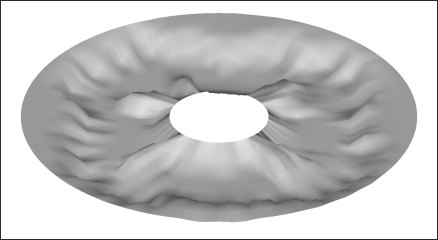
Figure 2.4: Solution for the default pattern method.
Since the default reinforcement pattern is almost symmetric, a cyclically symmetric pattern can be used to clean up the solution. Choosing four wedges for cyclical symmetry appears to be very close to the pattern created with the default settings. The cyclical symmetry pattern grouping type is applied. The DTPG card for the cyclical symmetry method is shown below.
(1)
|
(2)
|
(3)
|
(4)
|
(5)
|
(6)
|
(7)
|
(8)
|
(9)
|
(10)
|
DTPG
|
1
|
PSHELL
|
1
|
|
|
|
|
|
|
+
|
5.0
|
60.0
|
YES
|
2.5
|
NORM
|
|
|
SPC
|
|
+
|
PATRN
|
41
|
0.0
|
0.0
|
0.0
|
0.0
|
1.0
|
0.0
|
|
+
|
PATRN2
|
4
|
1.0
|
0.0
|
0.0
|
|
|
|
|
For cyclical symmetry, both the first vector (fields 12, 13, and 14) and second vector are defined in the same plane as the disc. The anchor node is located at the center of the disc. This cyclical pattern is set up to have four symmetric wedges with each wedge being symmetric about itself.
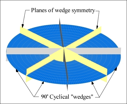
Figure 2.5: Cyclical symmetry pattern for 4 symmetric wedges.
The solution for the cyclical pattern grouping option is shown in Figure 2.6. OptiStruct generated a reinforcement pattern very similar to the default pattern grouping pattern but with fourfold symmetry. The modal frequencies were slightly less than those for the default pattern.
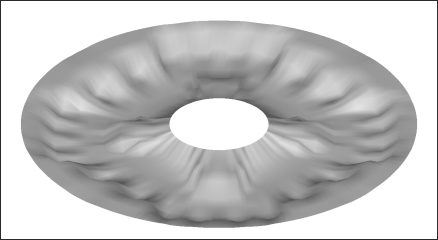
Figure 2.6: Solution for the cyclical pattern method with 4 symmetric wedges.
The frequency results (in Hz) for the first six normal modes for the baseline model and four reinforcement patterns are shown in the following table:
Mode #
|
Baseline
|
Circular
|
Radial
|
Default
|
Cyclical
|
1
|
18.7
|
47.3
|
45.3
|
51.1
|
50.4
|
2
|
18.7
|
47.3
|
45.4
|
52.7
|
50.4
|
3
|
20.1
|
73.0
|
43.8
|
69.1
|
68.5
|
4
|
34.8
|
61.5
|
60.2
|
66.3
|
66.7
|
5
|
34.8
|
61.5
|
60.6
|
68.4
|
67.5
|
6
|
74.4
|
113.0
|
93.0
|
115.0
|
117.0
|
For the input file sample, see <install_directory>/demos/hwsolvers/optistruct/disc_radial.fem and <install_directory>/demos/hwsolvers/optistruct/disc_cyclic.fem.
See Also:
Manufacturability for Topography Optimization


