|
»Click here to display Table of Contents«
|

Contact Interfaces |

|

|

|

|
|
Contact Interfaces |
|
|

|

|
|
»Click here to display Table of Contents«
|
Contact Interfaces |
|
|
|
|
|
Contact Interfaces |
|
|
|
|
No, only the external surface of the solid should be defined. As of RADIOSS V9.0, it is possible to define the surface of an external skin of a solid part (or a subset, a material, a property, and so on) with the option /SURF/PART/EXT. With older RADIOSS versions, this surface should be built using segments (a surface type /SURF/SEG will be created but no additional element added). |
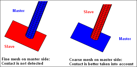
It is recommended to choose the coarse mesh on the master side for better contact detection. In the following example, contact is not detected if the fine mesh is chosen on the master side.
In case both meshes are of the same size, the stiffer structure on the master side should generally be choosen. |
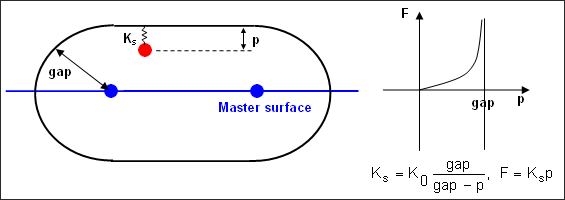
The interface stiffness is a non-linear function of the penetration p and goes to an infinite value when the slave node gets very close to the master segment in order to prevent the node from crossing the master segment and hence, better represent contact. The initial stiffness K0 (that is to say the stiffness when the node enters the gap), computed by RADIOSS takes into account either both master and slave stiffness (flag Istf equals 2 to 5) or only master stiffness (old way corresponding to Istf =0). The stiffness is computed according to geometrical and material characteristics of the elements on master side and/or on slave side (depending on the value of Istf). For shell elements:
where, E is the Young modulus of the material and t is the thickness of the shell. For solid elements:
where, B is the Bulk modulus of the material, A is the area of the segment and V is the volume of the solid element. Stfac is a scale factor which you can modify with a default value equal to 1. |
First check the gap that is used for this interface: The value must be physically realistic and based on shell thicknesses in case of contact between shells. In case of constant gap (Igap =0) with no input gap (Gapmin=0), RADIOSS determines a default value for Gapmin and you can check this value in the listing file (Runname_0000.out). Also check stiffness' on slave and master side. If they vary by a ratio greater than 100, the stiffer structure must be on the master side for Istf =0 so that the interface initial stiffness will be greater and even though the interface initial time step will be lower this will increase the time step if penetration is large. Indeed the penetration will be lower for the same energy absorption and thus for “stopping the slave node”. The following formula estimate the stiffness on slave and master side: For shells:
where, E is the Young modulus of the material and t is the thickness of the shell. For solids:
where, B is the Bulk modulus of the material, A is the area of the segment and V is the volume of the solid element. If it is necessary to keep the less stiff structure on the master side (for instance because its mesh is coarser), the value for the interface stiffness factor Stfac can be changed in order to increase the interface initial stiffness (otherwise the default value 1 for Stfac is generally well-suited). Stfac can then be set to the following value:
The previous method of choosing the maximum stiffness between master side and slave side would be automatically set up with Istf =3; but it may still be necessary to use other ways of setting the interface stiffness in case the stiffness of master and slave side are very different. If some elements fail on the master side or on the slave side of the interface, it is important to set Idel =2 (or Idel =1) for this interface. This will prevent nodes connected to deleted elements whose stresses are released to impact with a possible high velocity. |
WARNING ID: 94** WARNING IN INTERFACE GAP INPUT GAP xxx HOWEVER GAP IS RECOMMENDED TO BE LESS THAN xxx
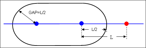
This message is especially important in case of a self-impacting interface. The recommended value corresponds to the smallest side length of shell elements on the master side, divided by 2. Shown below is a self-impacting interface for which the GAP equals half the side length of an element. If this element is compressed more than 50%, the red node enters into the gap of the neighboring element. A self-contact is then detected (which may not happen). This leads to over stiffening of the structure.
So the message means that at least one element on the master side has a side length less than twice the GAP and there is a risk of over stiffening. If the side length L of an element is lower than the GAP, a self contact will be computed from the beginning of the computation. Such a situation can be accepted if it is local enough, but not if it is a frequent situation over the self-impacting interface. It is possible to find the source of this message by using a pre-processor and selecting the elements through size criteria. If the interface is not self-impacting, possible consequence of this message will be low performance, but the model behavior will be correct. |
This message can be written by RADIOSS Engine. Such an error message may appear during sorting of contact interfaces when the distance between some nodes of the model becomes infinite. One has to look at the model behavior to understand why some node coordinates are infinite. One common explanation is "flying" nodes after failure of elements belonging to interface surfaces. In this case using Idel =2 in contact interfaces should fix this problem. |
Detecting the slave nodes and master segments which are in contact, a spatial sort is necessary. Even if using high performance sort algorithms, a full sort at each cycle would not be a fast enough solution. So during sorting, impacts within some security distance up to the gap are retained. The frequency of interface sorting, that is to say the security distance up to the GAP for storing the candidates to the impact, relies on the parameter Bumult. It is recommended not to change its value (which is by default 0.20), since it has been determined in order to optimize the performances, based upon our experience. |
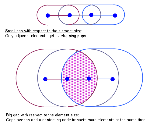
WARNING ID: 460** WARNING IN SIZE OF INFLUENCE ZONE INFLUENCE ZONE IS TOO BIG COMPARED TO ELEMENT SIZE, MULTIMP SHOULD BE GREATER THAN 12 FOR INTERFACE 1, OR THE VALUE OF THE GAP SHOULD BE DECREASED (SEE RECOMMENDED GAP) POSSIBLE IMPACT NUMBER: 0 (< = 1 * NSN) For each interface, RADIOSS Starter estimates the necessary memory size in case all slave nodes would impact the master surface at the same time. This memory size would be more important if the GAP is big, with respect to the master elements size, since an impacting node would impact a larger number of master elements at the same time. If this leads to a larger estimated memory size than the memory allocated for this interface, it would be possible for RADIOSS Engine to stop with the error “Infinite Loop Detected”, depending on the behavior of the model. RADIOSS Starter writes these recommendations so that one can adjust the GAP value (which should be physical enough), and/or increase the value of Multimp for this interface and this will lead to more memory allocation for this interface.
|
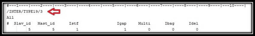
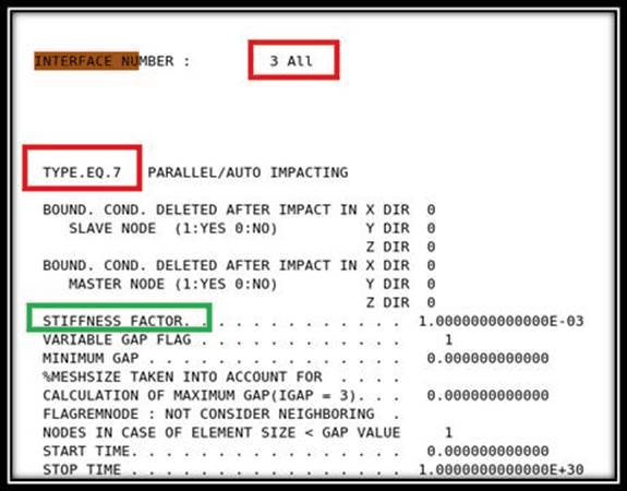
Interface type 19 is a combination of interfaces type 7 and type 11. In the output file *0.out, the message about interface type 19 will be output separately under interfaces type 7 and type 11. For example, interface type 19 with the title “All” in the model is defined, as shown below:
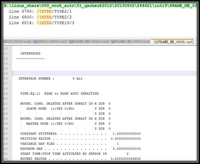
In the *0.out file, the follow message appears. There is no direct message for interface type 19.
|
The situation is quite usual. The problem is that we tie slave nodes of tetra elements to segments on the tetra elements. With spotflag=0, you do not have balanced moments, therefore, the more distance between slave and master, the worse (the higher) will the unbalanced forces be. Here the distance is app 15% of element size. A smaller distance will improve the situation. A larger distance will make it worse (general for solids and shells). For the shell on the master side, the situation is better because the shell nodes have rotational DOF. The tetra nodes have no rotational DOF (they are infinitely stiff against rotation) and give too much resistance in cases where the shell nodes would just rotate. For spotflag=1, transfer the forces from the slave to the master nodes, so that the force balance is assured and the level is not too high. When using interface TYPE2 contact, if under-integrated solid elements connected through TYPE2 contact with spotflag=0. This should be avoided. |