|
»Click here to display Table of Contents«
|

Time Step |

|

|

|

|
|
Time Step |
|
|

|

|
|
»Click here to display Table of Contents«
|
Time Step |
|
|
|
|
|
Time Step |
|
|
|
|
First, check which object is responsible for the low time step in the listing file (Runname_nnnn.out) of RADIOSS Engine. It can be an element, a node or an interface.
Check the size of the element, since where, lc is the characteristic length of the element, c is the material sound speed, and dtsca is the scale factor.
If a master node of a rigid body gives the time step, check the rigid body inertia reported in the listing file (Runname_0000.out), at: Rigid Body Initialization (for a rigid body made of only a few nodes, it may be necessary to set a spherical inertia).
|
For this time step computation, RADIOSS Starter does not take into account the damping coefficients; while RADIOSS Engine does. Particularly for thick beams, due to flexural damping, the time step computed by Engine may be quite different from the one computed by Starter.
|
For a rigid body and nodal time step, the time step for stability is computed at the master node (the nodal time step at slave nodes does not need to be considered). The time step computed at the master node of the rigid body is:
Where, M is the mass of the rigid body l is the lower principal inertia of the rigid body inertia matrix around the master node K is the stiffness reported to the master node
S is the slave node Kr is the rotation stiffness reported to the master node
S is the slave node D being the distance from slave to master node. The time step at the master node of the rigid body is computed by reporting stiffness at slave nodes to the master node. The mass and inertia of the rigid body depends on the flag ICoG in /RBODY. If ICoG =4, the mass that is input in the rigid body option is considered; whereas for ICoG =2, the mass that is input in the rigid body option is added to the slave nodes mass. |
Yes, it is possible. First check that the inertia which has been given to the rigid body is correct. Check the rigid body inertia as it is reported in the listing file (Runname_0000.out), at: RIGID BODY INITIALIZATION If the conditioning of the inertia matrix is bad, either because the slave nodes are aligned or because there are only a few slave nodes, it is recommended to set Ispher =1 for the rigid body in order to use a spherical inertia. |
The input file probably includes an Interface Type 7, Type 10 or Type 11.
For an impact between a slave node and a master segment, the stiffness of the penalty spring for this impact is applied to both slave and master nodes, in order to ensure stability. More precisely, Interface Type 7 associates a penalty spring and damping, so that an equivalent stiffness to the whole system is considered. The nodal stability time step is computed as follows:
where, M is the nodal mass and K is the nodal stiffness
If the deck includes Interface Type 7, Type 10 or Type 11, this time step is always computed at all nodes of the deck, in order to ensure stability even if an elementary time step is used. When the time step is taken onto a node, this node is probably impacting (otherwise nodal time step computed with |
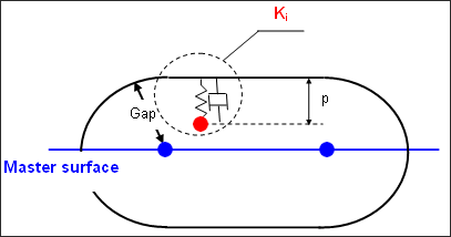
The interface kinematic time step avoids the slave nodes to cross the master surface.
where vr is an estimation of the maximum relative speed between master nodes and slave nodes. This time step computation prevents a slave node from crossing the master surface while ensuring the performances of searching the contacts through the interface.
If this time step is lower than the value given in option /DT/INTER/DEL, the slave node is suppressed from the interface and the following message is written to the listing file of RADIOSS Engine: **WARNING MINIMUM TIME STEP 0.3001E-03 IN INTERFACE 1 REMOVE SLAVE NODE 526210 FROM INTERFACE
In certain situations, the kinematic time step of the interface may be lower than the minimum time step which was specified in option /DT/INTER/DEL. If such a situation is encountered from the beginning of the computation, the value of the Gap may be checked. |
These messages are related to the option /DT/INTER/DEL. They both consist in the slave node suppression from the interface. This node will no longer impact any master segment for this interface.
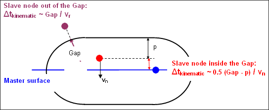
The message "Remove Slave Node" is written when the interface kinematic time step is lower than the minimum time step; which was specified in option /DT/INTER/DEL. For the slave/master couple which is considered, the kinematic time step is:
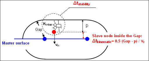
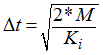
If it is such that The message "Delete Slave Node" is written when the stability time step of the interface for the slave/master couple; which is considered is lower than the minimum time step which was specified in option /DT/INTER/DEL. The stability time step for the slave/master couple is computed as follows:
where, M is the minimum nodal mass among the slave node and the nodes of the master segment, and Ki is the interface stiffness for the slave/master couple which is considered (Ki is an equivalent stiffness to the penalty spring and the damping which are applied between the slave node and the master segment). When the stability time step for the slave/master couple is such that It is possible that those messages would be written several times within the same cycle for the same node and the same interface (if the node impacts several master segments within the same cycle and several contacts get a lower time step than the minimum time step which was specified in option /DT/INTER/DEL). |